¶ Example 2: Saturated-Unsaturated Flow
¶ 1. Introduction
Example 2 is the steady state simulation of a varied saturated flow problem.
¶ 1.1 Problem Domain
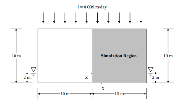
The region of interest is bounded on the left and right by two symmetric drains (20 m apart), on the bottom by an impervious aquifuge, and on the top by an air-soil interface.
¶ 1.2 Problem Discretization
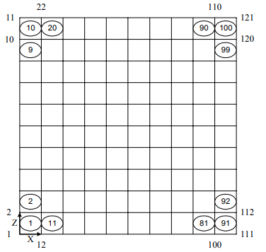
The simulation region is discretized with 10×10 = 100 elements and 11×11 = 121 nodes with the element size of 1×1 m for each element.
¶ 1.3 Material Properties
The medium is assumed to have a saturated hydraulic conductivity of Kxx = Kzz = 0.01 m/day and Kxz = 0 dm /day, a porosity of 0.25 and a field capacity of 0.05.
The unsaturated characteristic hydraulic properties of the medium are given as:
θ=θ_r+(θ_s-θ_r ) A/(A+|h-h_a |^B ) (3)
and
k_r=((θ-θ_r)/(θ_s-θ_r ))^n (4)
where h_a = 0 m, A = 10 m2, B = 2, θ_s = 0.25, and θ_r = 0.05 are the parameters used to compute the water content and n = 2 is the parameter to compute the relative hydraulic conductivity.
¶ 1.4 Initial Condition
A pre-initial condition is set as h = 2− z which means the pre-initial water table is located at z = 2 m.
We can create 11 groups along x direction to represent the changes of pressure head.


| Module | Condition | Type | Group Name | Value |
|---|---|---|---|---|
Flow |
Initial Condition | Point | Hydrological_Initial_z_0 | 2 |
Flow |
Initial Condition | Point | Hydrological_Initial_z_1 | 1 |
Flow |
Initial Condition | Point | Hydrological_Initial_z_2 | 0 |
Flow |
Initial Condition | Point | Hydrological_Initial_z_3 | -1 |
Flow |
Initial Condition | Point | Hydrological_Initial_z_4 | -2 |
Flow |
Initial Condition | Point | Hydrological_Initial_z_5 | -3 |
Flow |
Initial Condition | Point | Hydrological_Initial_z_6 | -4 |
Flow |
Initial Condition | Point | Hydrological_Initial_z_7 | -5 |
Flow |
Initial Condition | Point | Hydrological_Initial_z_8 | -6 |
Flow |
Initial Condition | Point | Hydrological_Initial_z_9 | -7 |
Flow |
Initial Condition | Point | Hydrological_Initial_z_10 | -8 |
¶ 1.5 Boundary Condition
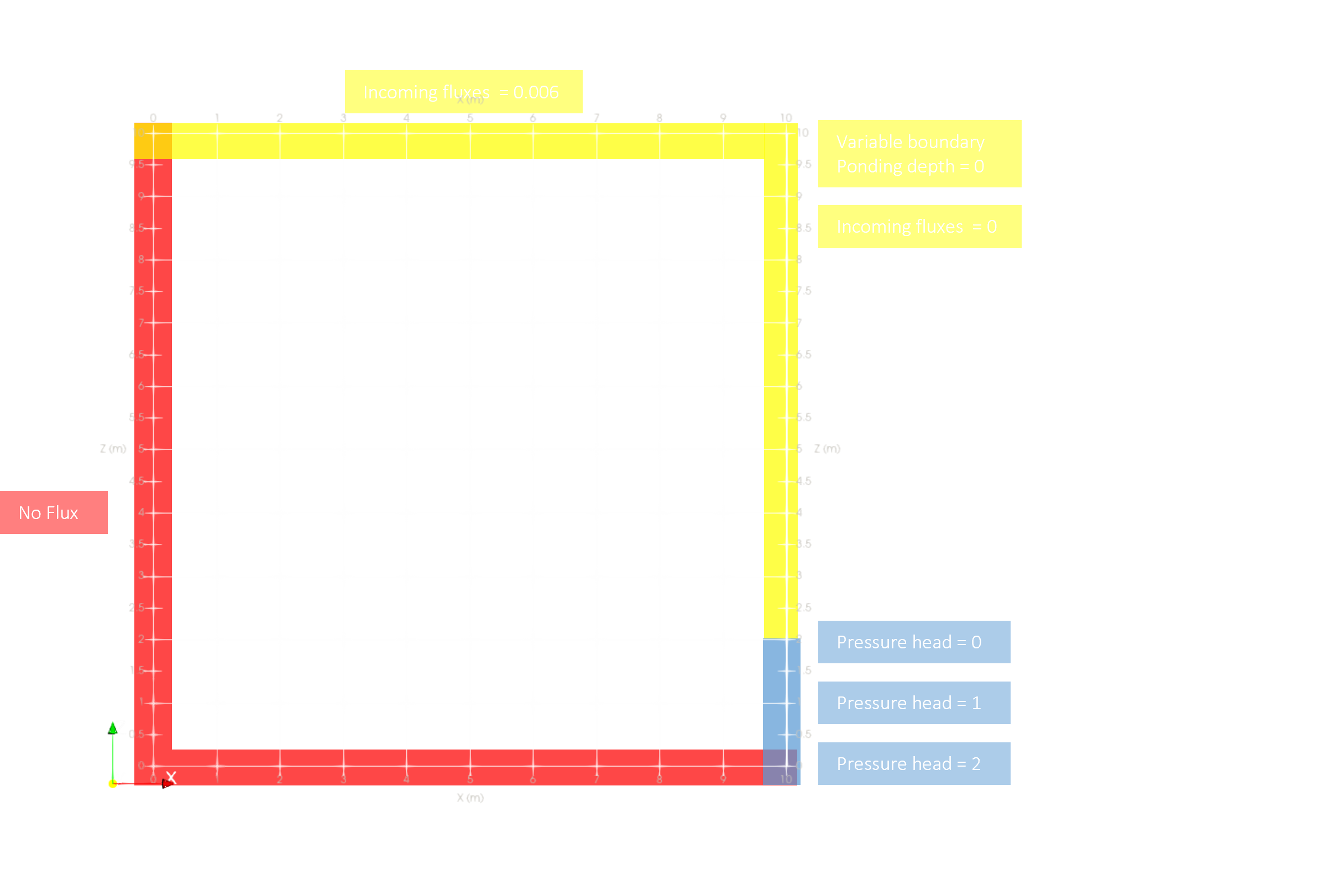
- No flux is imposed on the left (x = 0 m) and bottom (z = 0 m) sides of the region
- Dirichlet boundary:
Pressure head is assumed to vary from zero at the watersurface (z = 2 m)to2 m at the bottom (z = 0 m)on theright side (x = 10 m) - Variable boundary:
Ponding depth is assumed to be 0 m for all variable boundary surfaces- The incoming fluxes of variable boundaries are assumed equal to
0.006 m/dayfor the top surfaces - Equal to zero for the right side above the water surface
- The incoming fluxes of variable boundaries are assumed equal to
| Module | Condition | Type | Group/Domain | Value |
|---|---|---|---|---|
Flow |
Variable Condition | :material-vector-line: Edge | Hydrological_Variable_Surface | Profile 1 |
Flow |
Variable Condition | :material-vector-line: Edge | Hydrological_Variable_Right | Profile 2 |
Flow |
Dirichlet Condition | :material-vector-point: Point | Hydrological_Dirichlet_right | Profile 3 |
| ID | Time (day) | Flux (dm3/day) | Flux (m3/day) |
|---|---|---|---|
| Profile1 | 0.0d0 | -6.6D-2 | -6.6D-5 |
| Profile1 | 1.0d38 | -6.6D-2 | -6.6D-5 |
¶ 1.6 Expected Result
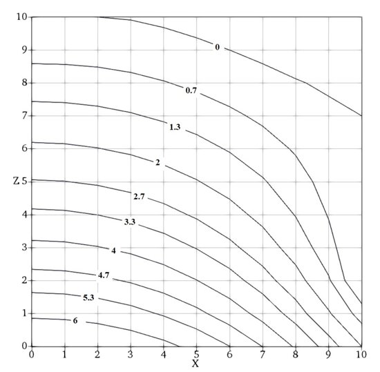
The pressure head tolerance for nonlinear iteration is 2×10⁻³ m. The pressure head distribution is shown by contours below.
¶ 2. Step-by-step Tutorial
¶ 2.1 Create the Project
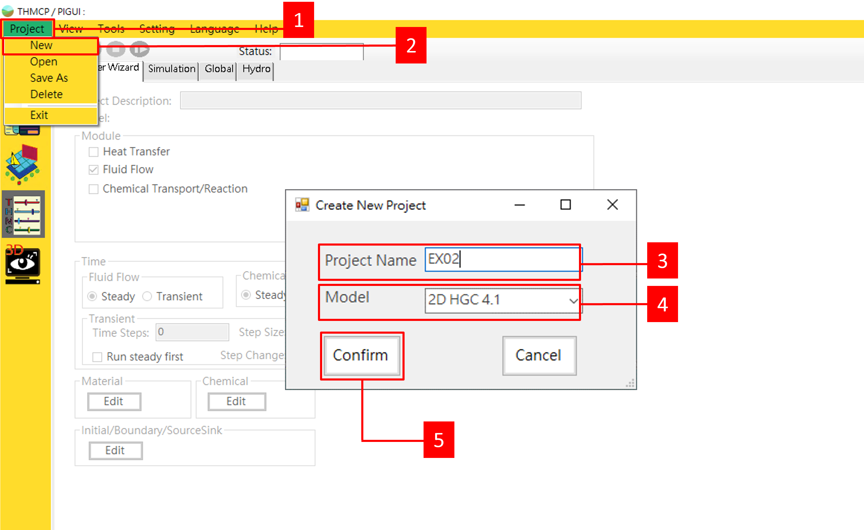
| Parameter | Value |
|---|---|
| Project Name | EX02 |
| Model | THMC2D |
- Select Project
- Then New. The
Create New Projectdialog will appear. - Type in
Project NameEX02. - Select
ModelTHMC2D. - Click the Confirm.
¶ 2.2 Create Mesh
¶ 2.2.1 Create a new mesh solution
-
Switch to
 ^^GM GUI^^.
 -
Click File.
-
Click New or Open Solution. The
New or Open Solutiondialog will appear.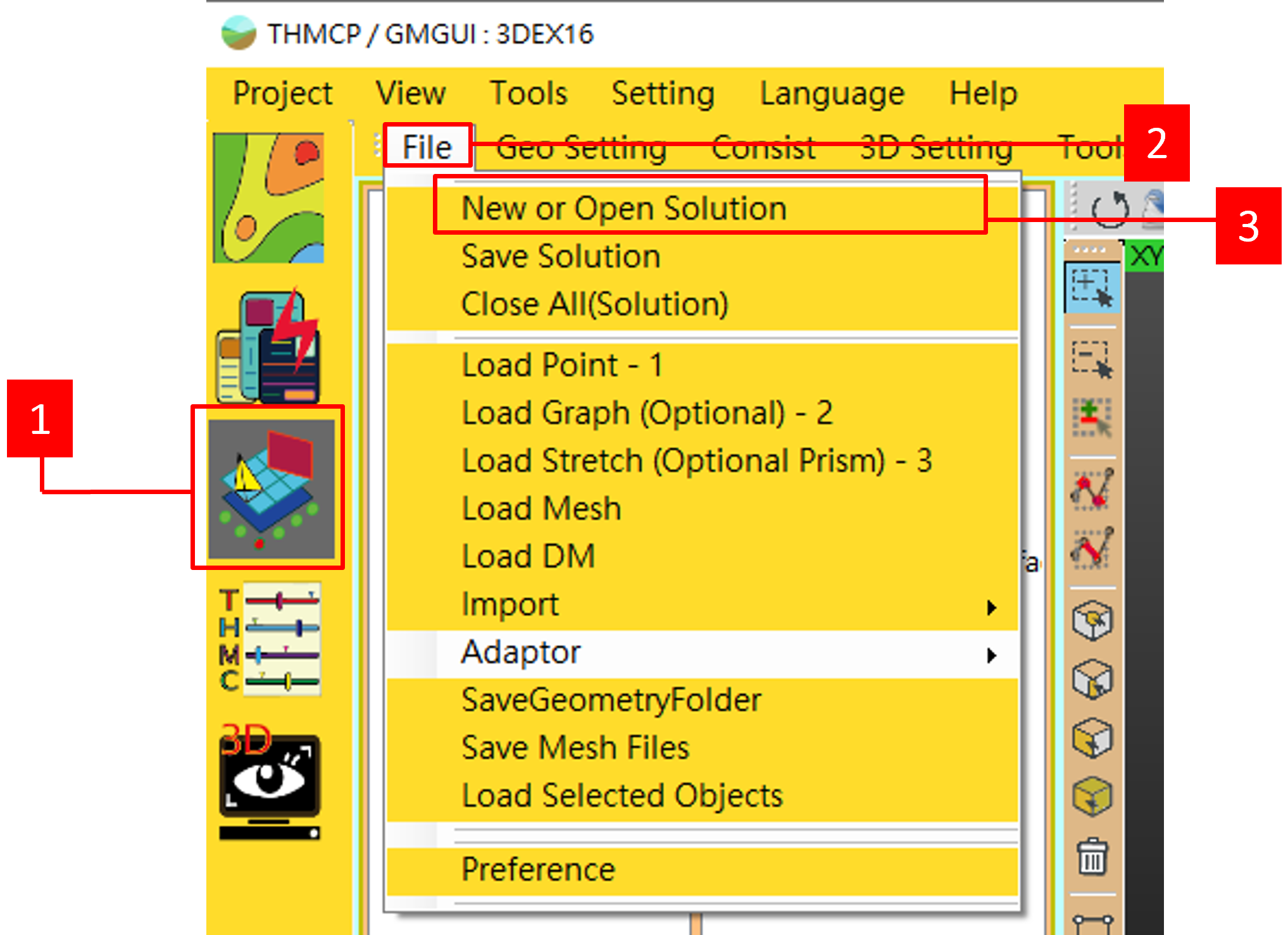
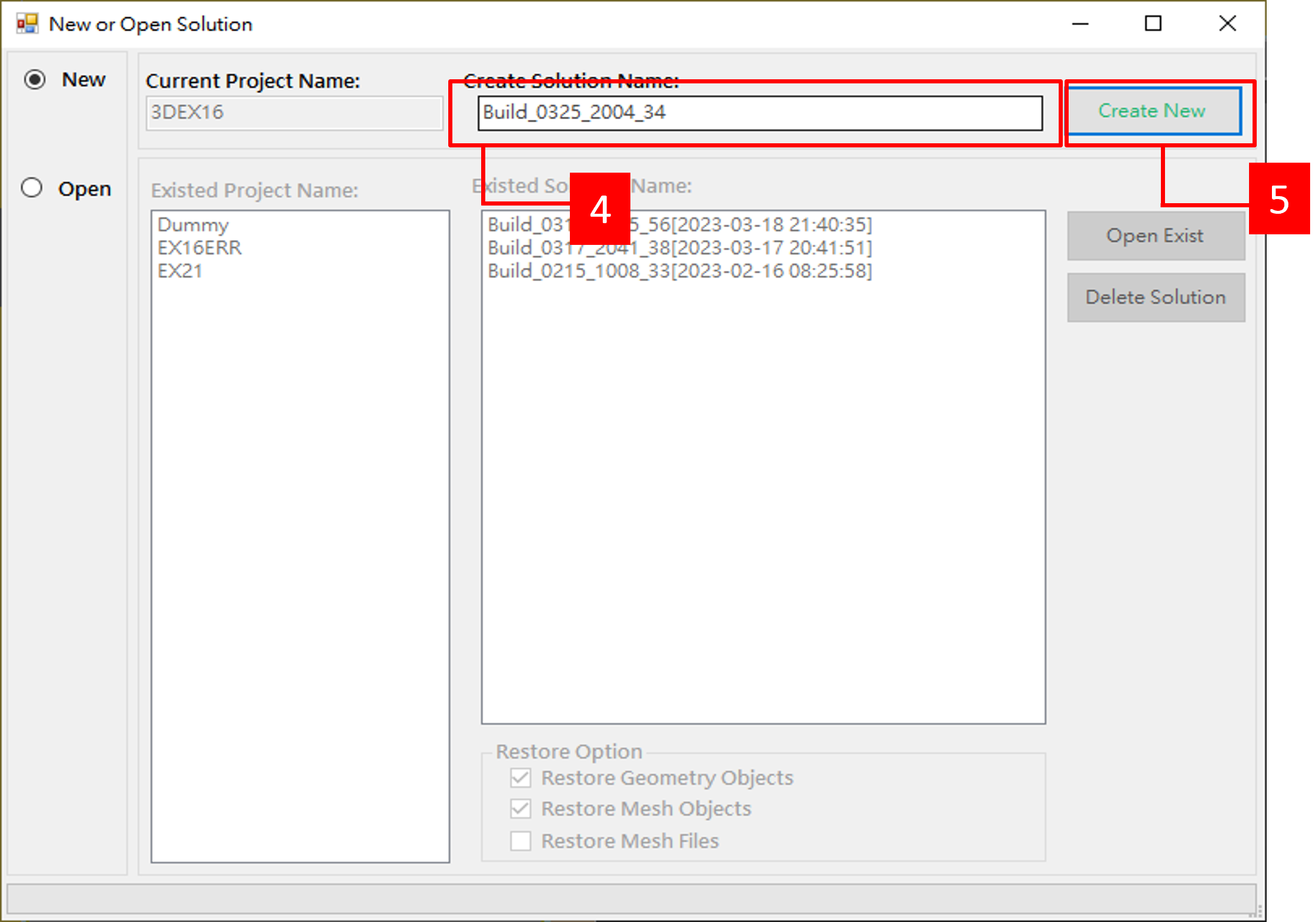
-
Type in
Solution Name. -
Click Create New.
¶ 2.2.2 Create a square domain
| Parameter | Value |
|---|---|
| Plane | ZX Plane |
| Shape | Square |
| W | 10 |
| H | 10 |
- Set Plane to
ZXPlane. - Click Square on left tool box.
- Set Rectangular to
W:10,H:10 - Click Preview.
- Click Complete.
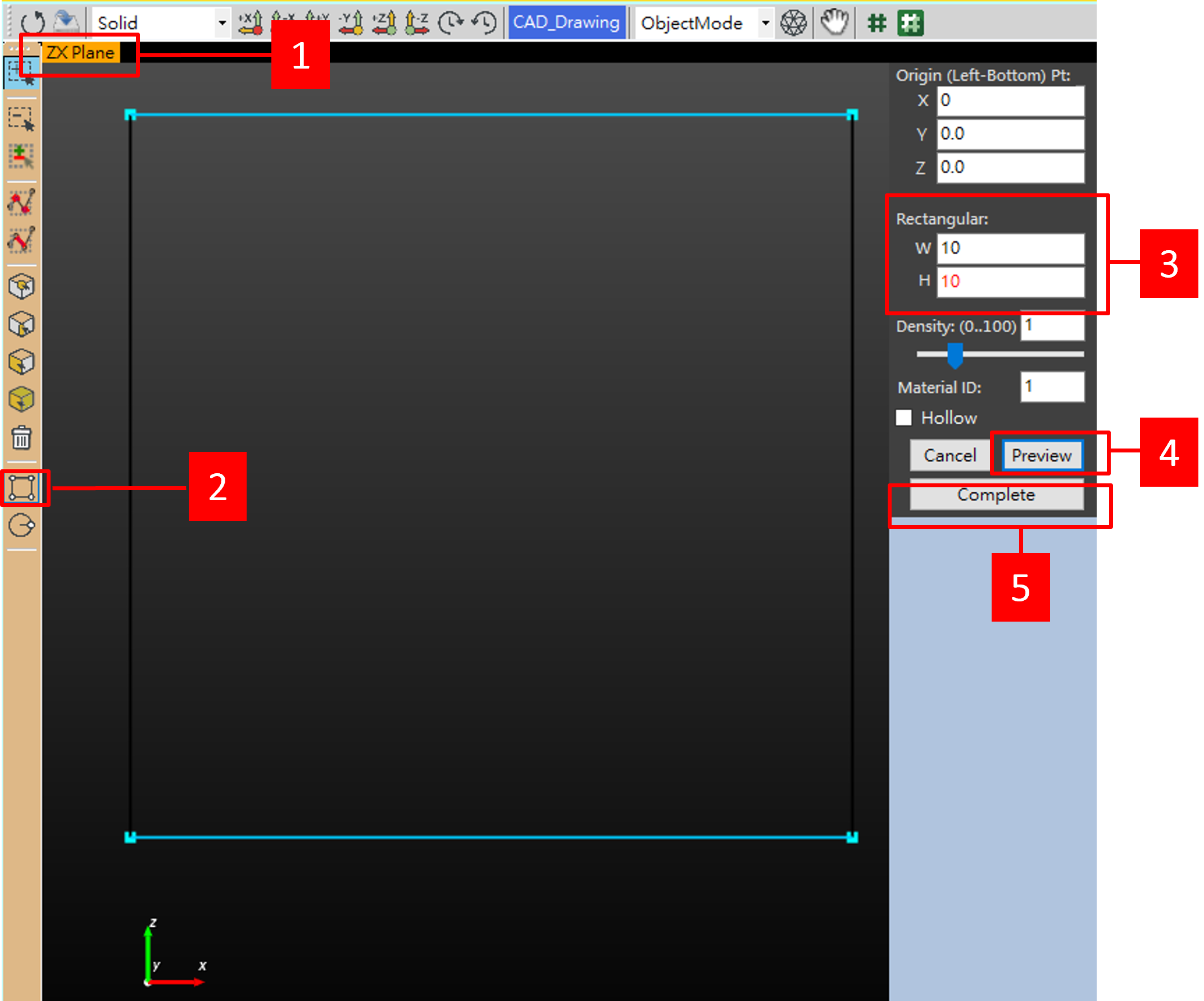
¶ 2.2.3 Generate mesh
| Parameter | Value |
|---|---|
| Mesh | Quadrilateral |
| Set Nodes Count | 11 |
-
Select Geo Setting.
-
Then click Smart Quadrilateral.

-
Mouse right click at
GEO, set all nodes Clockwise (for generating counter-clockwise nodes in each element). -
Type 11 next to Set Nodes Count then press Enter.
-
Clcik Mesh Generator. The
Mesh Generatordialog will appear.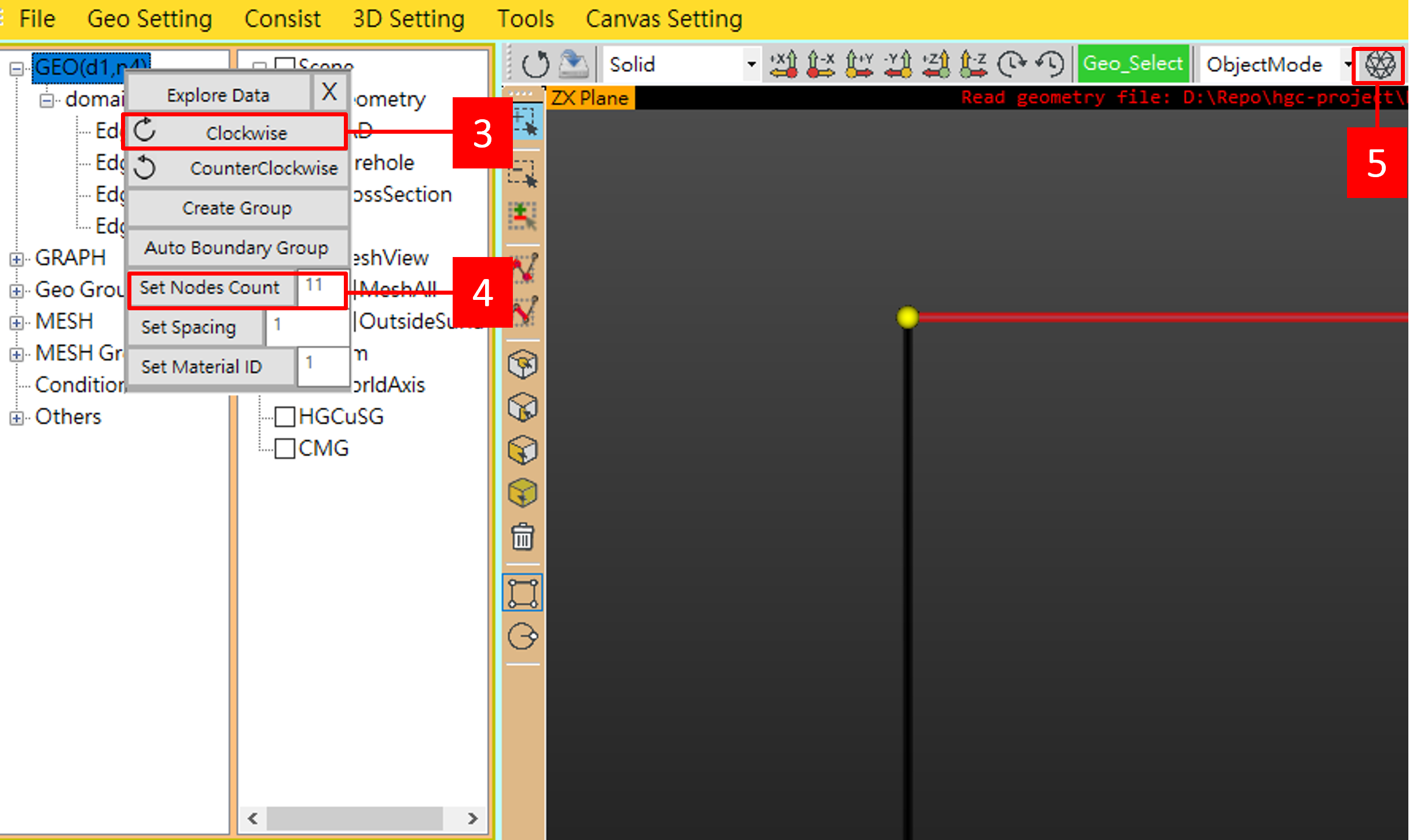
-
On
Mesh Generatordialog, click Quadrilateral.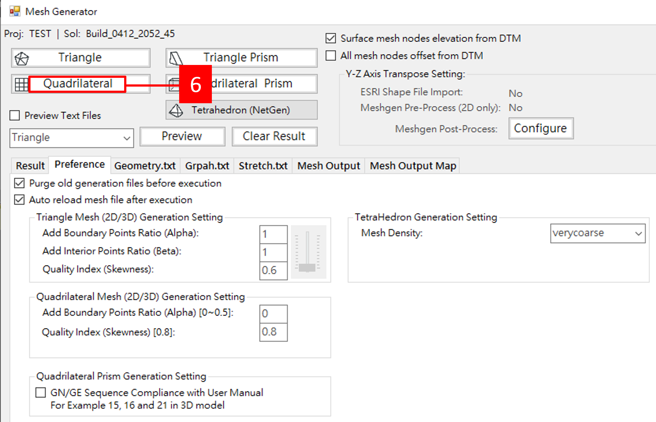
-
If mesh generated successfully, a quadrilateral mesh will appear.
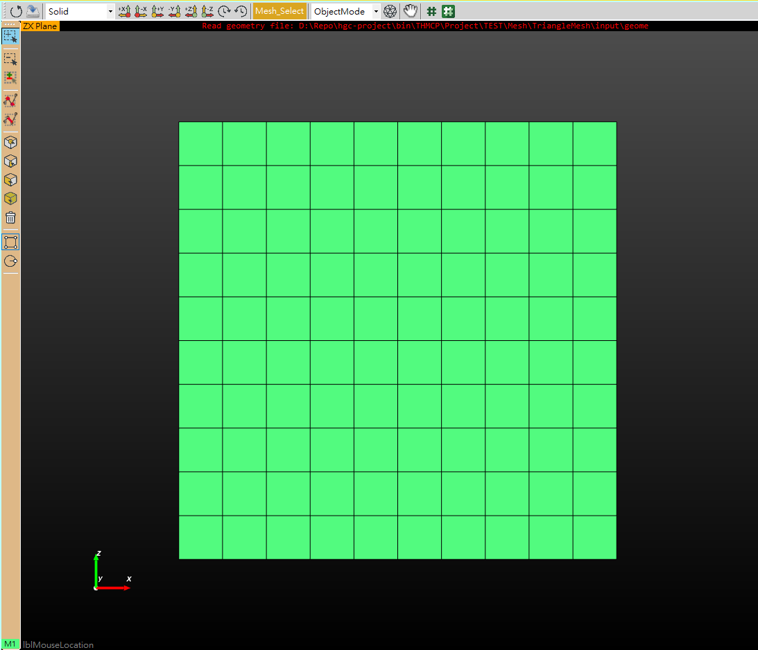
¶ 2.3 Create Geometry Groups
¶ 2.3.1 Create initial condition group
| Module | Condition | Type | Group/Domain |
|---|---|---|---|
Flow |
Initial Condition | Point | Hydrological_Initial_z_0 |
Flow |
Initial Condition | Point | Hydrological_Initial_z_1 |
Flow |
Initial Condition | Point | Hydrological_Initial_z_2 |
Flow |
Initial Condition | Point | Hydrological_Initial_z_3 |
Flow |
Initial Condition | Point | Hydrological_Initial_z_4 |
Flow |
Initial Condition | Point | Hydrological_Initial_z_5 |
Flow |
Initial Condition | Point | Hydrological_Initial_z_6 |
Flow |
Initial Condition | Point | Hydrological_Initial_z_7 |
Flow |
Initial Condition | Point | Hydrological_Initial_z_8 |
Flow |
Initial Condition | Point | Hydrological_Initial_z_9 |
Flow |
Initial Condition | Point | Hydrological_Initial_z_10 |
-
On left toolbox, click Add Selection.
-
Then click Select Nodes.
-
Draw a rectangular that cover all points on
z = 0.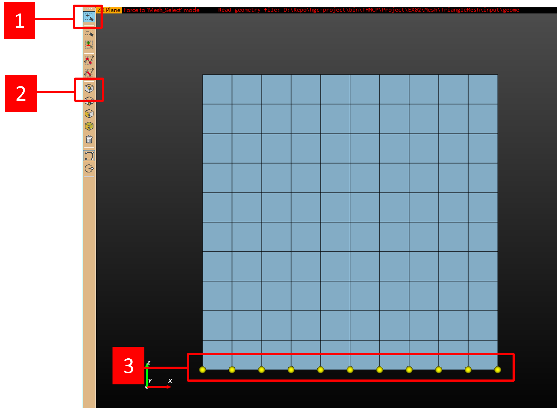
-
On Left-bottom table, click Create group. The
Create groupdialog will appear.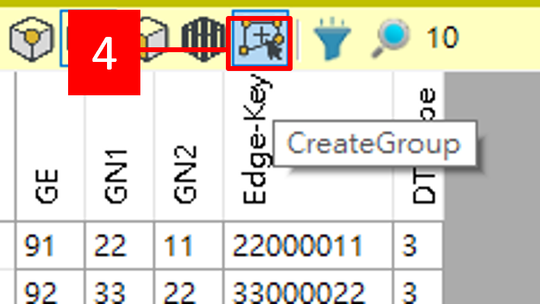
-
Set
Group Nameas Hydrological_Initial_z_0. -
Click Apply.
-
Then click Close.
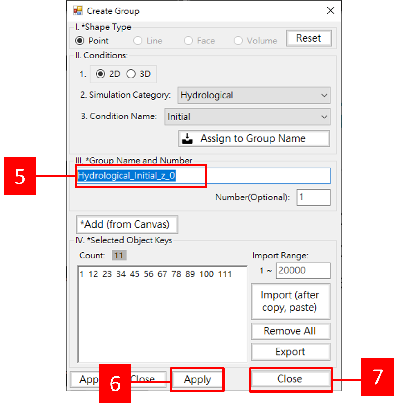
-
Repeat step 1 to 7, Create 11 groups from
z = 0toz = 10.
¶ 4.2 Create boundary group
¶ 4.2.1 variable boundary
| Module | Boundary | Type | Group/Domain |
|---|---|---|---|
Flow |
Variable | Edge | Hydrological_Variable_Surface |
Flow |
Variable | Edge | Hydrological_Variable_Right |
¶ 4.2.2 Dirichlet boundary
| Module | Boundary | Type | Group/Domain |
|---|---|---|---|
Flow |
Dirichlet | Point | Hydrological_Dirichlet_right |
¶ 4.3 Save solution
-
Select File.
-
Then click Save Solution. The
Save Geometrydialog will appear.
-
Check
Quadrilateral. -
Then click OK.

¶ 5. Set Simulation Properties
¶ 5.1 Import Mesh
- Click to start mesh import form as Import Mesh
- Change unit as
m - Select mesh
- Click Import to import mesh and boundary created from
GMGUI.
¶ 5.2 Set Material Properties
- Set Hydraulic Conductivity
Kxx=Kzz= 0.01 m/day andKxz= 0 dm /day - Set Porosity
Setporosityas 0.25 (Saturated Water Content) and Field capacity(Residualmoisture content) = 0.05 - Set Water Retention Curves
h_a= 0m,A= 10 m2,B= 2,θ_s= 0.25, andθ_r= 0.05 are the parameters used to compute the water content andn= 2
¶ 5.3 Set Global Variables
- Check View/Advanced to edit readonly parameters.
- Set solver unit as
m
¶ 5.4 Set Module Variables
| Module | #DATA SET | #Record | Variable | Value |
|---|---|---|---|---|
Flow |
3 | 4 | KGRAV | 1 |
Flow |
3 | 4 | IPNTSF | 0 |
Flow |
3 | 5 | IVMLF | 0 |
- Click
Hydrotab to edit Flow module parameters - Click on
Data Sets/Recordstree nodeDATA SET 3\Flow Record 4, and click onParametersdatagrid
- Set KGRAV to 1
- Set IPNTSF to 0
- Click on
Data Sets/Recordstree nodeDATA SET 3\Flow Record 5, and click onParametersdatagrid
- Set IVMLF to 0
¶ 6. Set Initial Condition and Boundary Condition
¶ 6.1 Set Flow Initial Condition
| Module | Condition | Group/Domain | Value |
|---|---|---|---|
Flow |
Initial Condition | Hydrological_Initial_z_0 | 2 |
Flow |
Initial Condition | Hydrological_Initial_z_1 | 1 |
Flow |
Initial Condition | Hydrological_Initial_z_2 | 0 |
Flow |
Initial Condition | Hydrological_Initial_z_3 | -1 |
Flow |
Initial Condition | Hydrological_Initial_z_4 | -2 |
Flow |
Initial Condition | Hydrological_Initial_z_5 | -3 |
Flow |
Initial Condition | Hydrological_Initial_z_6 | -4 |
Flow |
Initial Condition | Hydrological_Initial_z_7 | -5 |
Flow |
Initial Condition | Hydrological_Initial_z_8 | -6 |
Flow |
Initial Condition | Hydrological_Initial_z_9 | -7 |
Flow |
Initial Condition | Hydrological_Initial_z_10 | -8 |
¶ 6.2 Set Flow Boundary Condition
| Module | Boundary | Group/Domain | Ponding Depth(m) | Minimum Pressure Head(m) | 0 day | 1.0E38 day |
|---|---|---|---|---|---|---|
Flow |
Variable | Hydrological_Variable_Surface | 0 | 0 | 0.006 | 0.006 |
Flow |
Variable | Hydrological_Variable_Right | 0 | -9000 | 0 | 0 |
| Module | Boundary | Group/Domain | 0 day | 1.0E38 day |
|---|---|---|---|---|
Flow |
Dirichlet | Hydrological_Dirichlet_right | 2 | 2 |