¶ Brief
In this chapter, we will use the first example problem EX01(2D) in THMC benchmarks to demonstrate an end-to-end workflow for running a 2D vertical unsaturated flow simulation. Simulation process is shown on Figure 2.0
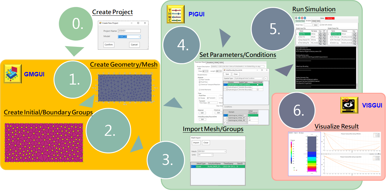
Figure 2.0 Simulation Process
Get the THMC software: 1.2.2 How to get THMC software
Install THMC: 1.2.3 How to install THMC software
¶ 2.0 Create Project
All datas are organized in a folder structure as following, and the root folder name is the project name, we need to create a project for the simulation. Steps as following:
└─THMC/
    ├─ Project/
    │   ├─ Project_1/
    │   │   ├─ Mesh/
    │   │   ├─ Solver/
    │   │   │   └─ HGC4.3 (or HGC5.3)/
    │   │   │       ├─ Output/
    │   │   │       │   ├─ Original/
    │   │   │       │   ├─ Flow/
    │   │   │       │   ...
    │   │   │       ├─ SIM.inp
    │   │   │       └─ SIM.dm
    │   │   └─ Project.xml
    │   ├─ Project_2/
    │   ...
| Parameter | Value |
|---|---|
| Project Name | EX01 |
| Model | THMC2D |
Table 2.1 Project Parameters
- To start a new project, move to the Main Menu and select
Project\New.
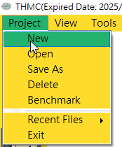
Figure 2.1 Create a new project
-
In the
Project Nametext field, enter "2DEX01". -
Since it is a 2D numerical simulation, select
THMC2DinModel, then clickConfirm.
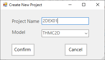
Figure 2.2 Set project name and model
¶ 2.1 Create Geometry/Mesh
¶ 2.1.1 Create a Solution for Mesh
Before we start to create the mesh for this example, we have to create a solution in the Geometry Mesh GUI. Steps as following:
- Go to the
The Geometry Meshmodule
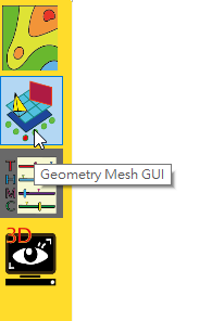
Figure 2.3 Click on The Geometry Mesh icon
- Start a new solution in the
Geometry Mesh GUI- Select
File\New or Open Solution.
- Select
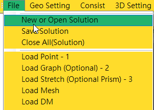
Figure 2.4 Create a new solution
- In the
New or Open Solutionwindow, enter the solution name and clickCreate New.
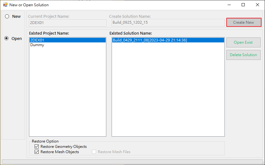
Figure 2.5 Set project name and model
¶ 2.1.2 Create the Geometry for the Mesh
| Parameter | Value |
|---|---|
| Plane | ZX |
| Shape | Square |
| W | 50 |
| H | 200 |
Table 2.2 Geometry Parameters
Before creating the mesh for our simulation, we have to create a single rectangular domain geometry for the mesh. Steps as following:
- Find the
Squareicon located on the left side toolbar of the Geometry Mesh GUI.
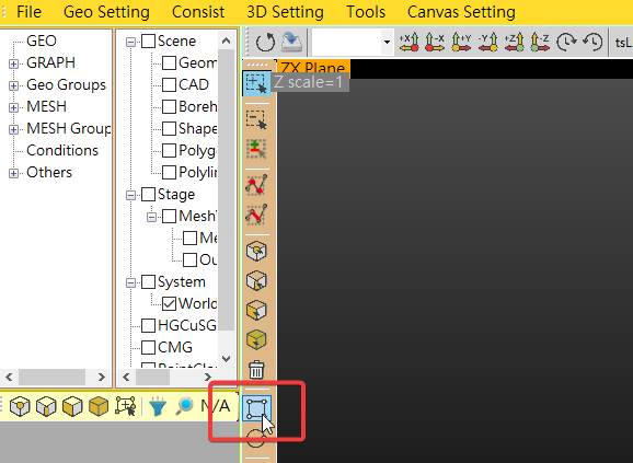
Figure 2.6 Click on the square tool
- A panel will then appear on the right side, under
Rectangularenter W=50 and H=200, click on thePreview. The geometry will be displayed on the screen.

Figure 2.7 Create a rectangular domain
- Then click the
Createbutton, a rectangular domain 50 by 200 will be actually created.
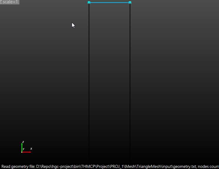
Figure 2.8 The rectangular domain
¶ 2.1.3 Create the Mesh
After creating the domain, we are going to create the actual mesh in the domain. We want to split the Z-direction of the domain into 40 segments, so there will be 40 elements in the resulted mesh. Steps as following:
| Parameter | Value |
|---|---|
| Mesh | Quadrilateral |
| BG1 Nodes Count | 41 |
Table 2.2 Mesh Parameters
- Find the
Mesh Generatoricon on the upper toolbar on theGeometry GUI, then click it.
![]()
Figure 2.9 Mesh Generatior Icon
- In the pop-up window, click the
Quadrilateralbutton. Then the window will close automatically, and there will be a surface that fills the domain we just created.
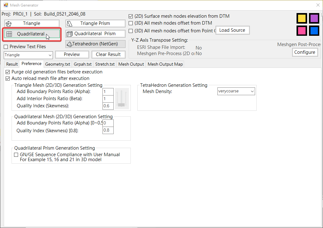
Figure 2.10 Mesh Generator
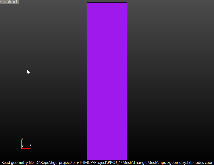
Figure 2.11 A surface in the domain
- In the left side of the
Geometry GUI, find the first nodeGEO(d1, n4)of the tree structure. Expand on the node, find the first child nodedomain1to expand its child nodes, there will be 4Edgeand 4BGunder it.
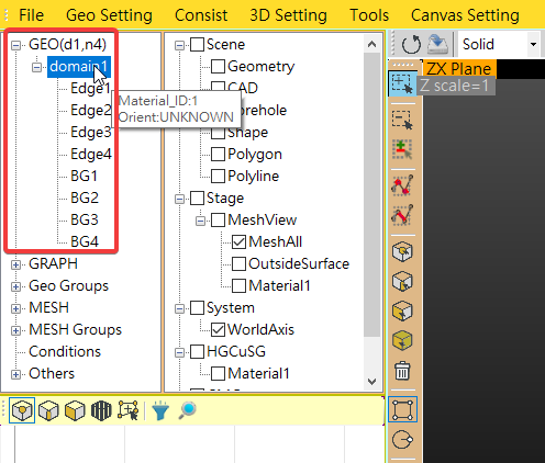
Figure 2.12 Expand the child nodes under domain1
- Find the
BG1node, when you click on the node, two ends of the correspondingBG1will be selected on the filled domain. We can find that 'BG1' is a Z-direction edge on the domain. In order to split the domain into 40 elements, we need to split the two ends (nodes) on the edge into 41 nodes.
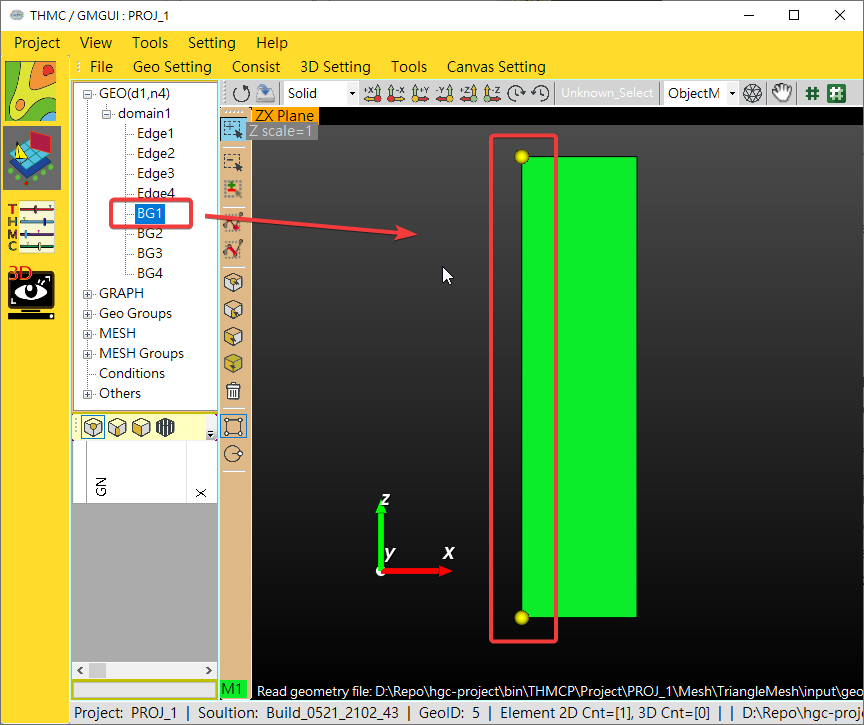
Figure 2.13 BG1 on the domain
- Then right-click on the
BG1node, a menu will be displayed. On the menu, find the text field next toSet Nodes Count, enter41then click onSet Nodes Count.
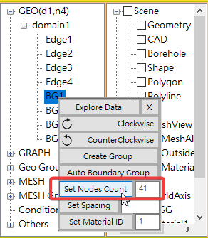
Figure 2.14 Set nodes count for BG1
- Then go back to the upper toolbar, find the
Mesh Generatorand click it to open the mesh generation tool. Then click theQuadrilateralbutton again. The window will close automatically, and there will be the final mesh with 40 elements that fills the domain.
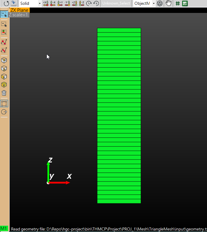
Figure 2.15 The final mesh
¶ 2.2 Create Initial/Boundary Groups
¶ 2.2.1 Create Mesh Groups for Initial Conditions
| Module | Condition | Type | Group/Domain |
|---|---|---|---|
Flow |
Initial Condition | Point | Hydrological_Initial_0 |
Flow |
Initial Condition | Point | Hydrological_Initial_-90 |
Flow |
Initial Condition | Point | Hydrological_Initial_-97 |
Table 2.3 Initial Condition Parameters
After obtaining the final mesh, we will create multiple groups of geometry objects for future assignments of initial and boundary conditions.
For instance, in this example problem, there are three distinct geometry groups within the mesh we just created for setting initial conditions: the top, the bottom, and the remaining mesh.
- Find the
Create Groupicon on the left toolbar on theGeometry GUI, then click it. In Benchmark problem 1 for the initial condition, since different values were input for the top, bottom, and the rest of the area of interest, we will specify initial conditions for each of these three parts separately.
![]()
Figure 2.16 The mesh generation tool
¶ 2.2.2 Create Mesh Groups for Boundary Conditions
- variable boundary
| Module | Boundary | Type | Group/Domain |
|---|---|---|---|
Flow |
Variable | Edge | Hydrological_Variable |
- Dirichlet boundary
| Module | Boundary | Type | Group/Domain |
|---|---|---|---|
Flow |
Dirichlet | Point | Hydrological_Dirichlet_right |
¶ 2.3 Import Mesh/Groups
¶ 2.4 Setting Parameters/Conditions
Follow Parameter Wizard to input parameters.
¶ 2.4.1 Define Initial Conditions
| Module | Condition | Group/Domain | Value |
|---|---|---|---|
Flow |
Initial Condition | Hydrological_Initial_0 | 0 |
Flow |
Initial Condition | Hydrological_Initial_-90 | -90 |
Flow |
Initial Condition | Hydrological_Initial_-97 | -97 |
¶ 2.4.2 Define Boundary Conditions
| Module | Boundary | Group/Domain | Ponding Depth(cm) | Minimum Pressure Head(cm) | 0 day | 10 day | 10.001 day | 1.0E38 day |
|---|---|---|---|---|---|---|---|---|
Flow |
Variable | Hydrological_Variable | 0 | -90 | 5 | 5 | -5 | -5 |
| Module | Boundary | Group/Domain | 0 day | 1.0E38 day |
|---|---|---|---|---|
Flow |
Dirichlet | Hydrological_Dirichlet | 0 | 0 |
¶ 2.5 Run Simulation
¶ 2.6 Visualize Result
¶ 2.6.1 Convert for Visualization
¶ 2.6.2 Create Visualization in ParaView
- Create Pressure View
- Create Pressure Head Profiles During Infiltration Line Chart
- Create Pressure Head Profiles During Evaporation Line Chart