¶ 4.1 Parameter Input GUI
¶ 4.1.1 Function Blocks
Function blocks as Fig. 4.1.1, include 3 blocks as following:
Tools and status bar: Provides grid import, simulation control and status functions.Page switching: You can switch to the parameter input wizard, simulation, general, water, chemical and thermal pages.Page operation block: parameter input or simulation operations can be performed on the page.
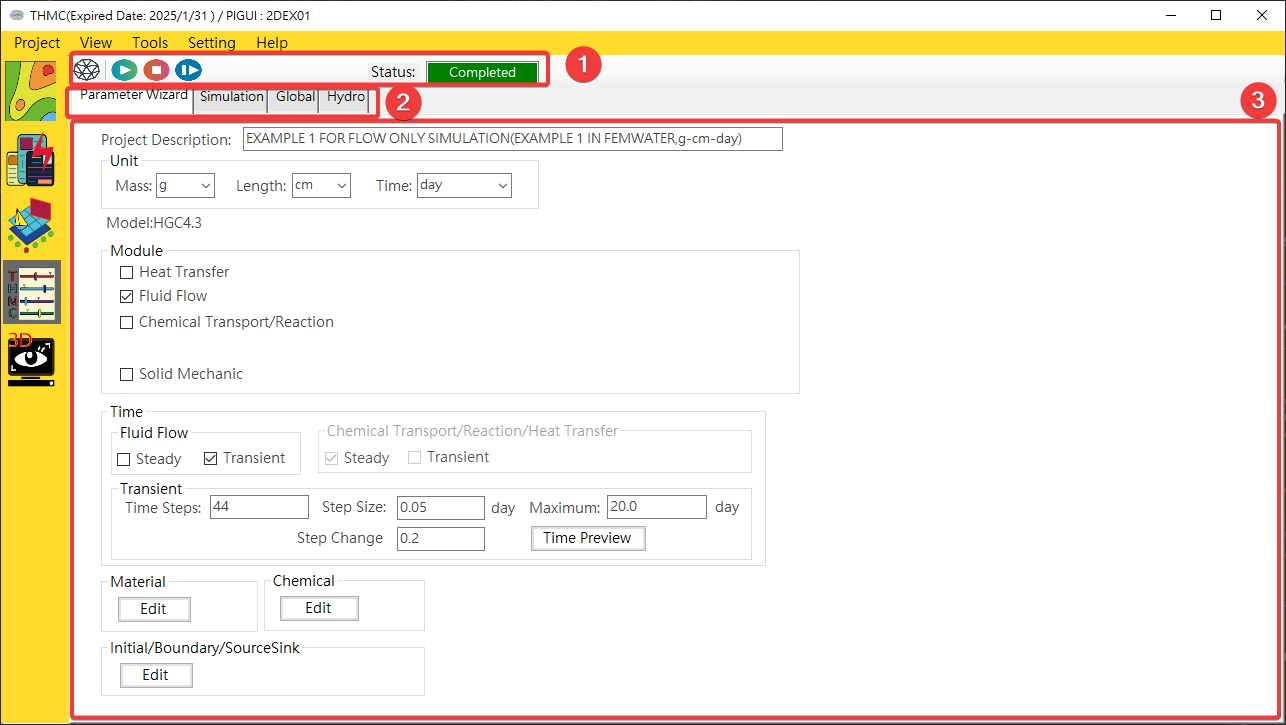
Fig. 4.1.1: Parameter input user interface function block description
¶ 4.1.2 Mesh Import
Mesh Import: For the mesh import function, you need to select the grid iconMesh Import Options: Select the grid scheme you want to use, select the grid length unit to import, and clickImport.
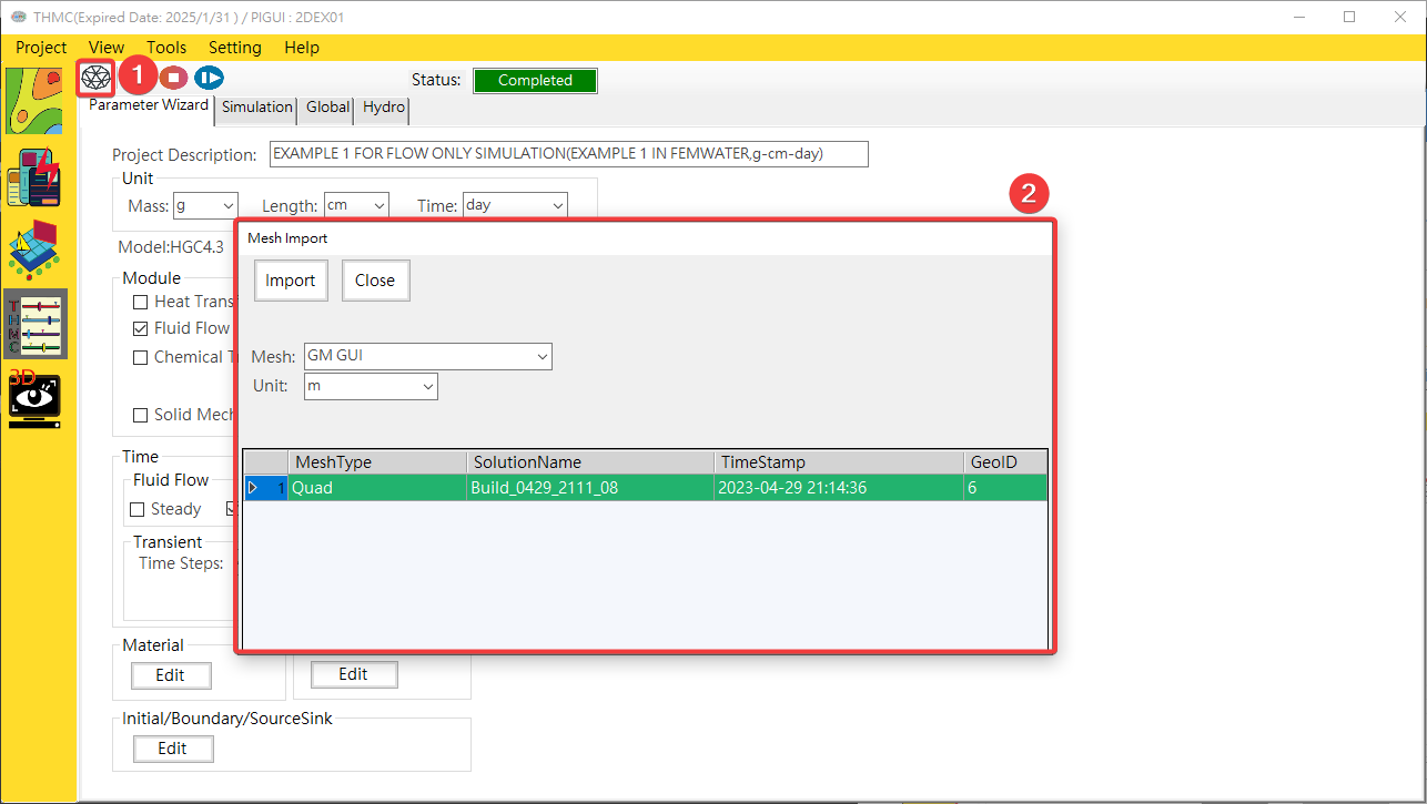
Fig. 4.1.2: Mesh Import
¶ 4.1.3 Parameter Wizard
Function blocks as Fig. 4.1.3, include 3 blocks as following:
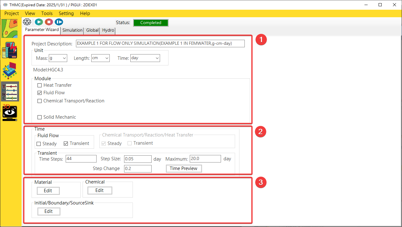
Fig. 4.1.3: Parameter Wizard Function Blocks
1: Project Information 2: Time Conditions 3: Module Conditions
Project Information: You can enter the project description and select the mode module, as shown inFig. 4.1.4.
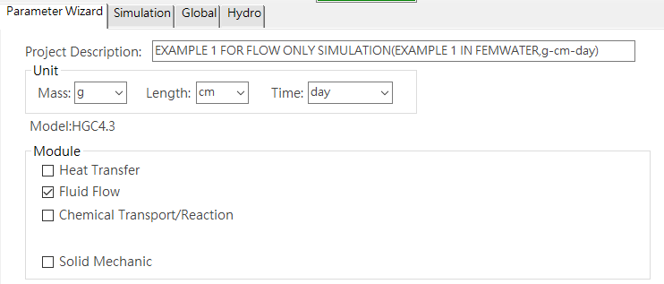
Fig. 4.1.4: Project Information
Time Conditions: Steady state or transient simulation can be set. If transient state is selected, the number of time steps and time interval must be set, as shown inFig. 4.1.5.
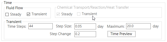
Fig. 4.1.5: Time Conditions
Module Conditions: including formation material conditions, chemical conditions and spatial conditions (initial conditions/boundary conditions/injection conditions).
a.Material Conditions: Provide material name and parameter input, as shown inFig. 4.1.6. In addition, the water flow parameters can be set to water retention curve parameters, as shown inFig. 4.1.7.
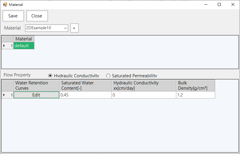
Fig. 4.1.6: Material Conditions
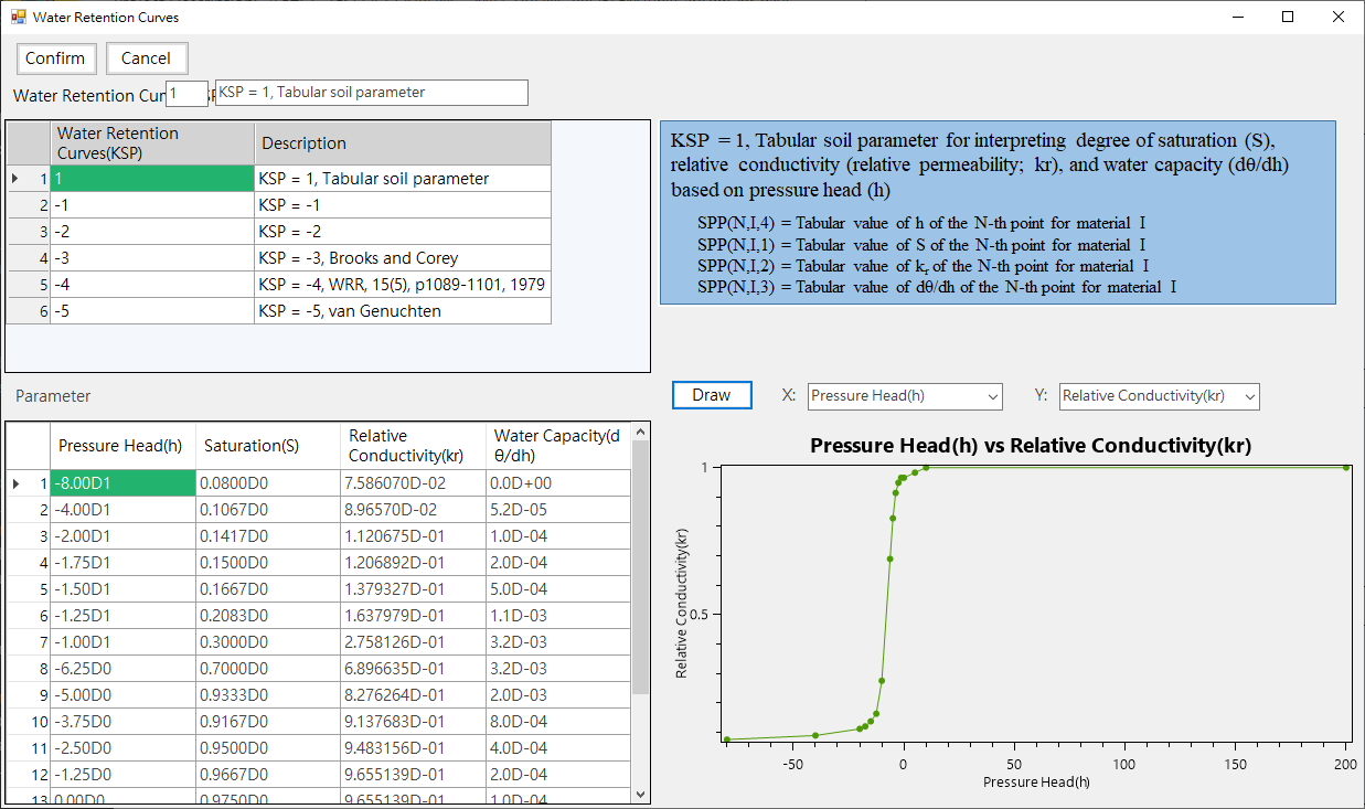
Fig. 4.1.7: Retention Curve Conditions
b. Chemical Conditions: Provide chemical reaction and species parameter input, as shown in Fig. 4.1.8. Click the Edit of Reaction Type column can set chemical reaction type parameters, as shown in Fig. 4.1.9.
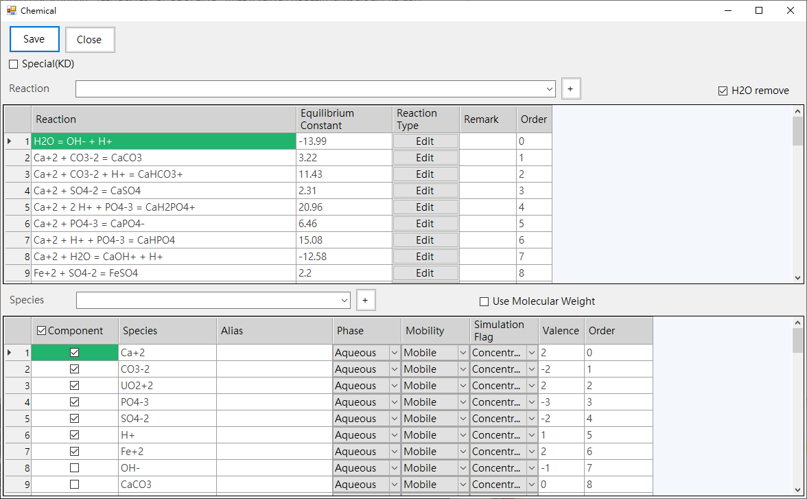
Fig. 4.1.8: Chemical Conditions
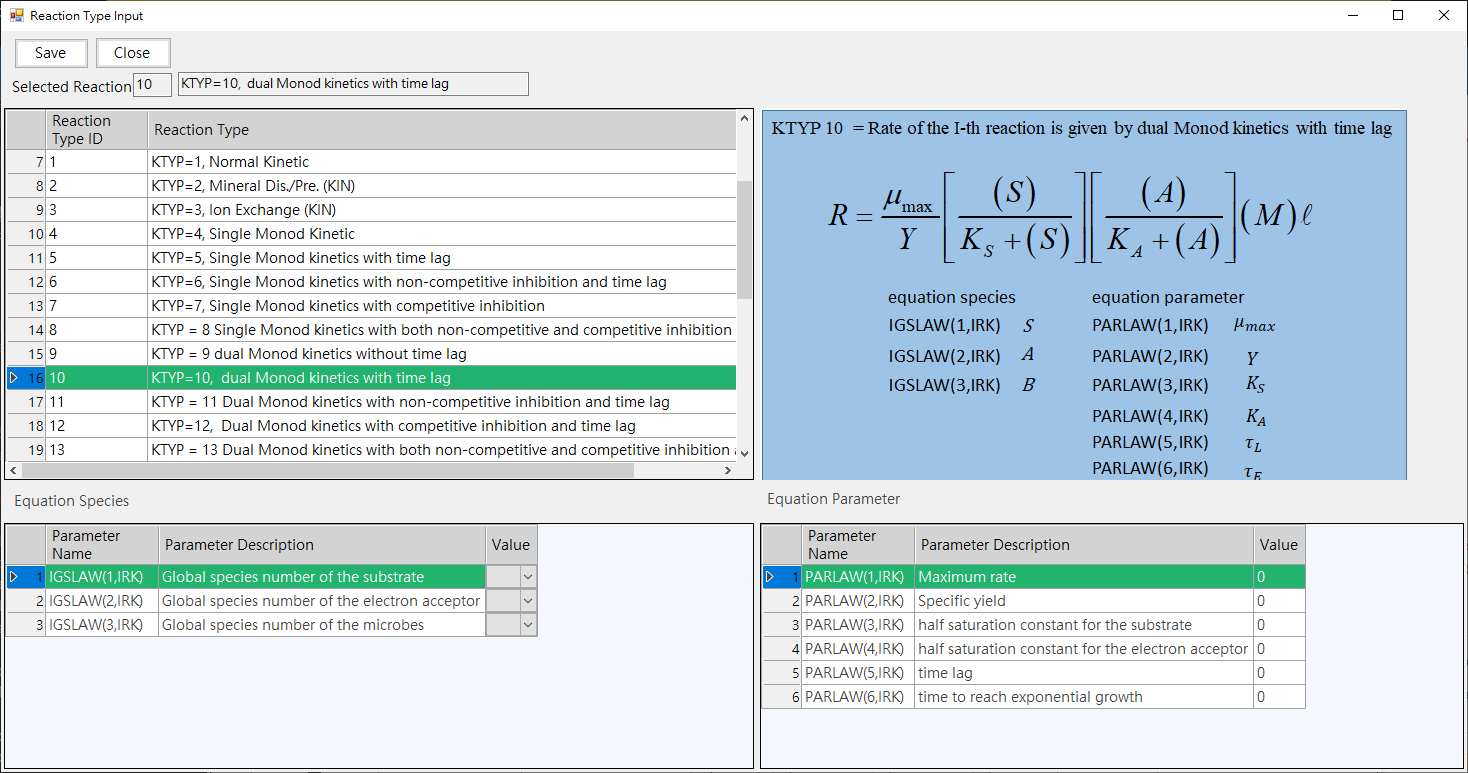
Fig. 4.1.9: Reaction Type Input
c. Spatial Conditions:
-Provide initial conditions/boundary conditions and injection condition parameter input, as shown in Fig. 4.1.10. Click Edit of Profile column to set parameter values that change with time, as shown in Fig. 4.1.11.
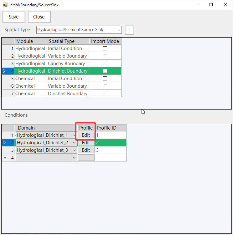
Fig. 4.1.10: Spatial Conditions
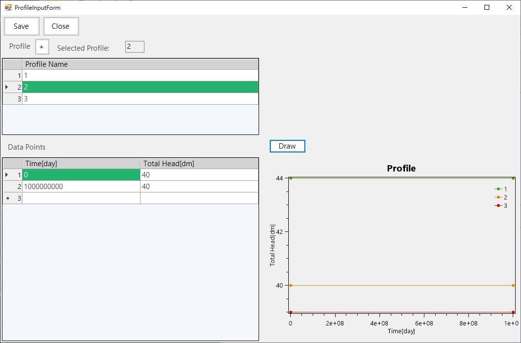
Fig. 4.1.11: Profile Input
-Provide chemical boundary species parameter settings, such as Fig. 4.1.12,
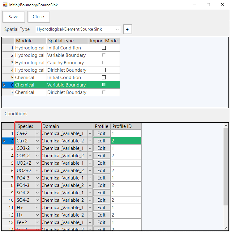
Fig. 4.1.12: Chemical Species
-Provides the function of setting initial conditions, as shown in Fig. 4.1.13,
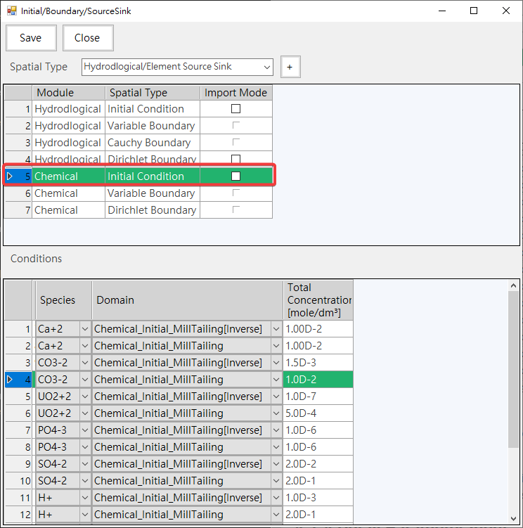
Fig. 4.1.13: Initial Condition
-Provides the function of importing initial conditions from text file, as shown in Fig. 4.1.14(follow step 1/2/3) and click 4. From Project to import initial conditions from the project, as shown in Fig. 4.1.15.
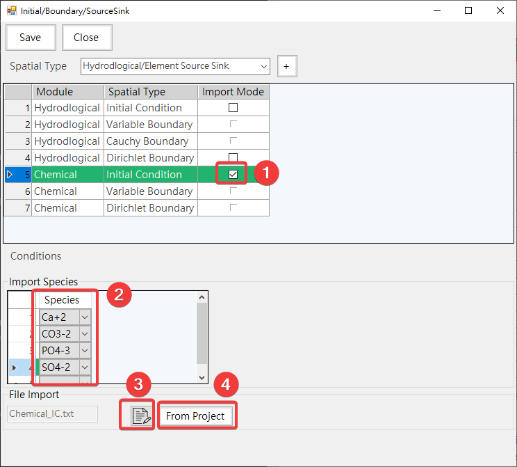
Fig. 4.1.14: Initial Condition Import Mode
1: Enable Import Mode 2: Select Species 3: Edit Import File 4: Click to Start Import From Other Simulation Project
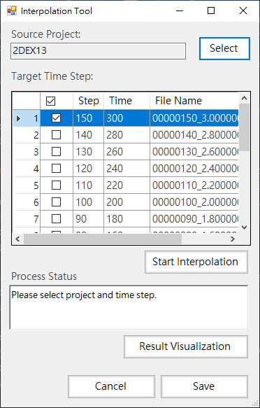
Fig. 4.1.15: Import from Other Project
¶ 4.1.4 Detail Parameter Input
For Global\Hydro\Chemical\Mechanics tab page has same function blocks as shown in Fig. 4.1.16
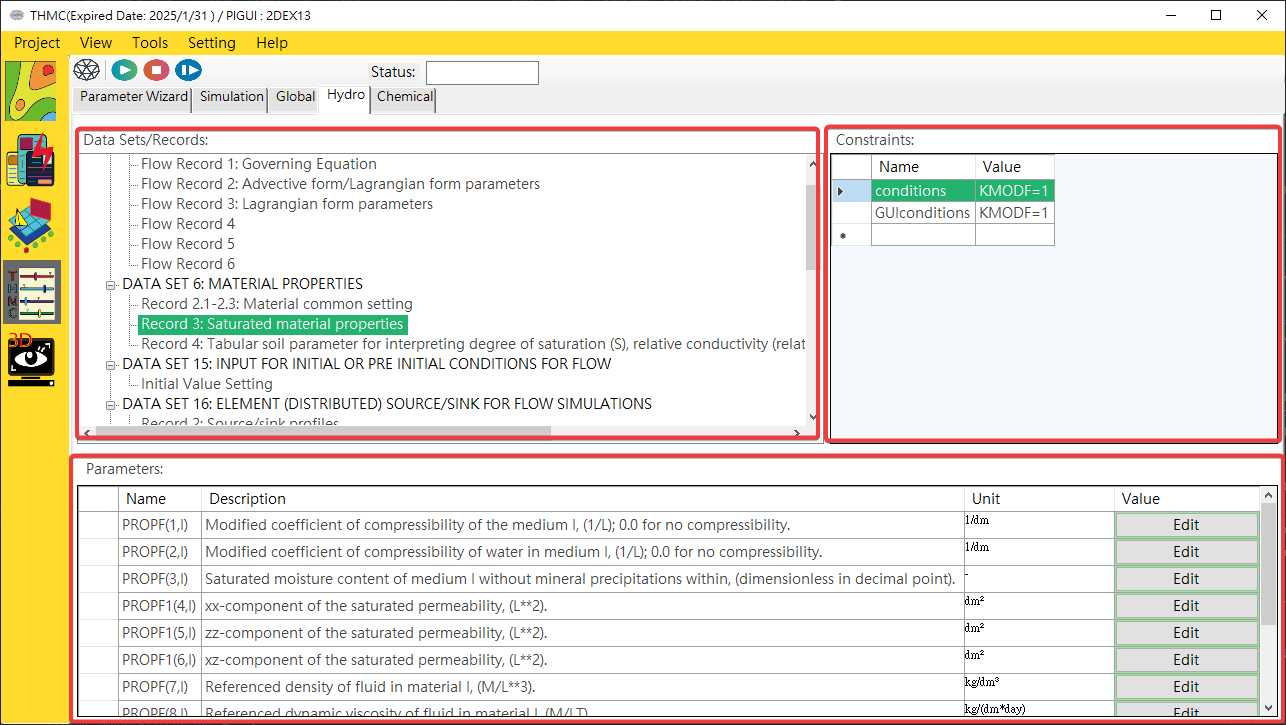
Fig. 4.1.16: Detail parameter input
Parameter Category: Data Sets/Records are the main/sub categories of parameters. Click on the items to view and modify parameters in the parameter block.Parameter Constraints: Displays Data Sets/Records restriction conditions to automatically bring out the parameters that need to be entered in the mode parameter block.Parameters: Use the mouse to click [View/Advanced Mode] on the platform function bar to switch to the advanced view mode. In the normal mode, only necessary parameters and information are displayed, while in the advanced mode, other information is displayed and can be edited and hidden. Parameters, as shown inFig. 4.1.17andFig. 4.1.18.
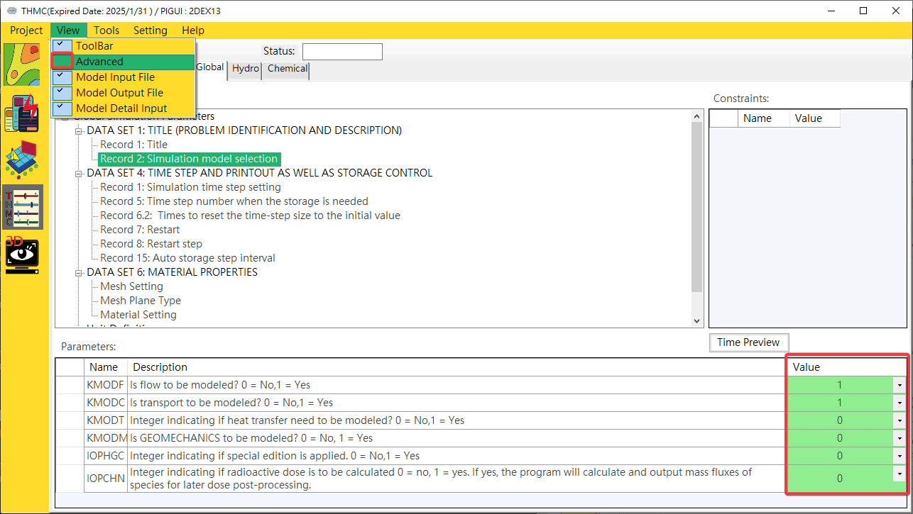
Fig. 4.1.17: Normal Mode
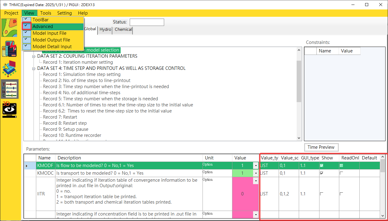
Fig. 4.1.18: Advanced Mode
- Single value parameter input UI features:
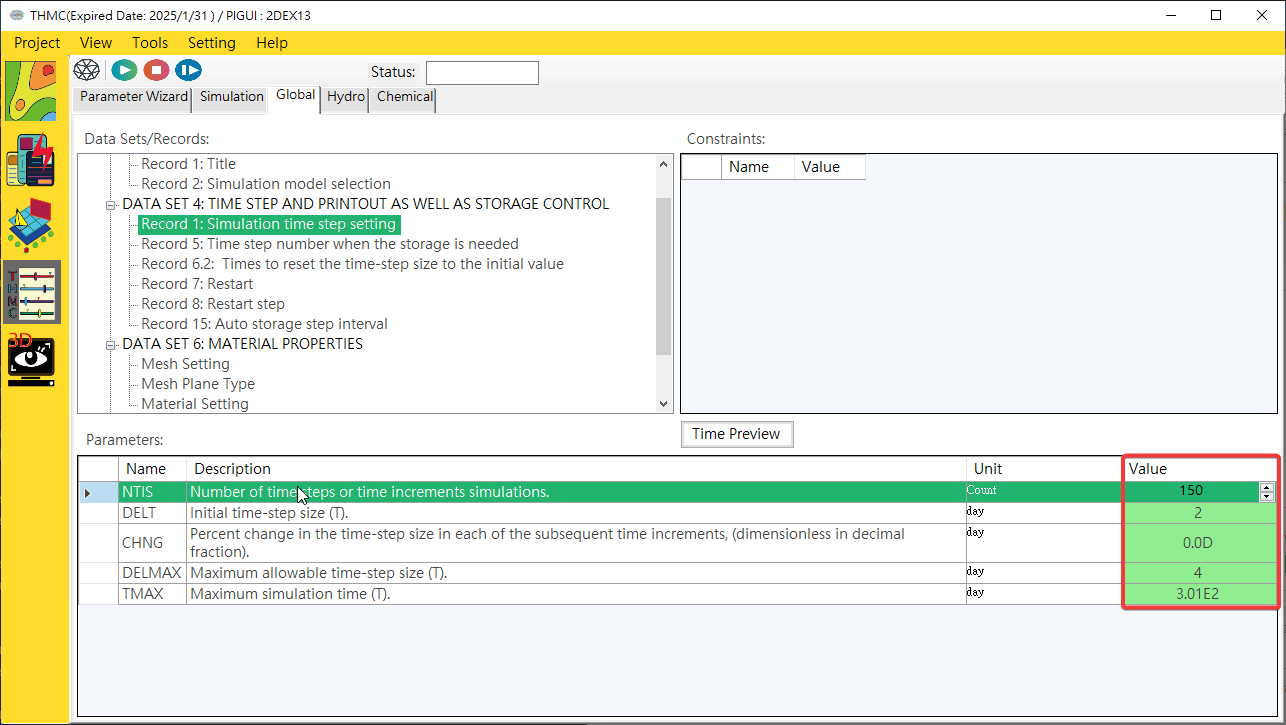
Provides a mode parameter editing interface with only a single value. Click the [Mode Parameter Block/Value] with the mouse to edit data, as shown inFig. 4.1.19.
- multivalue parameter input user interface functions:
Provides a multi-valued mode parameter editing interface. Click the [Parameter Input Block/Value] with the mouse, and a one- to three-dimensional multi-value parameter input user interface will pop up. Click on the content to edit data. One-dimensional, two-dimensional and Three-dimensional parameter content editing, as shown inFig. 4.1.20,Fig. 4.1.21andFig. 4.1.22.
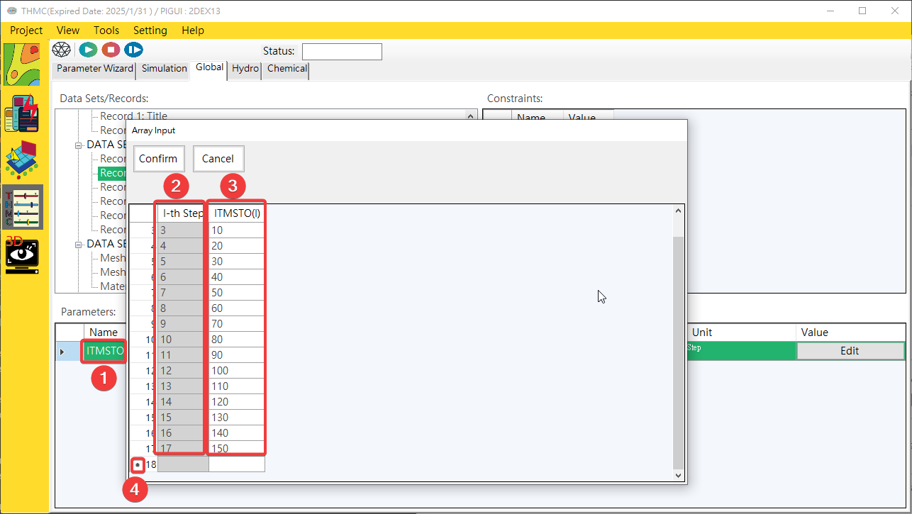
Fig. 4.1.20: One-dimensional Multi Values Parameter Edit UI
1: Parameter 2: 1D Index 3: Value Input Area 4: Add New
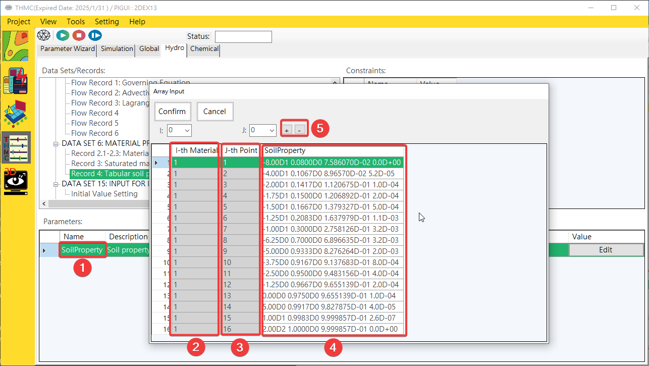
Fig. 4.1.21: Two-dimensional Multi Values Parameter Edit UI
1: Parameter 2: 1D Index 3: 2D Index 4: Value Input Area 5: Add/Delete
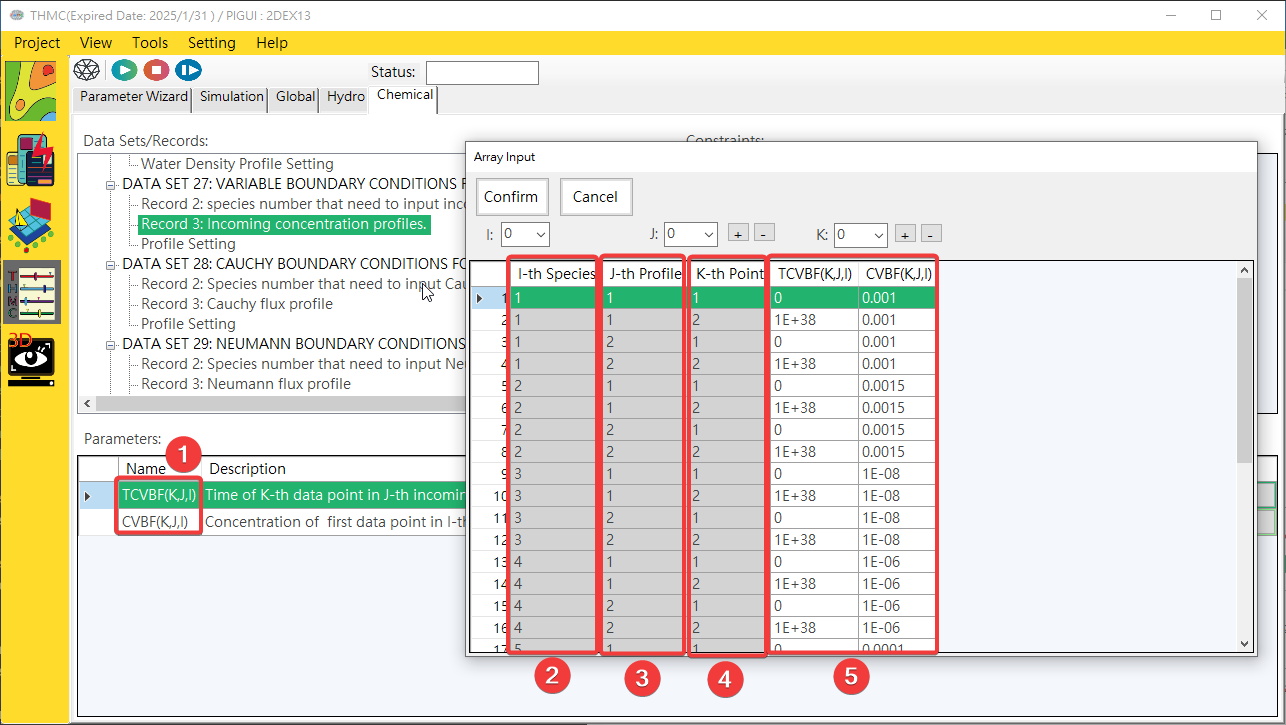
Fig. 4.1.22: Three-dimensional Multi Values Parameter Edit UI
1: Parameter 2: 1D Index 3: 2D Index 3: 3D Index 5: Value Input Area
¶ 4.1.5 Simulation Execution
The simulation execution user interface includes simulation control block, input and output file block and simulation log block. Each block is explained as follows. The simulation execution user interface function block is shown in Fig. 4.1.23.
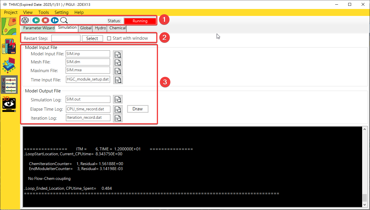
Fig. 4.1.23: Simulation Function Block
Simulation control block: Use the mouse to click on each function icon to execute start model simulation, stop mode simulation and restart mode simulation functions.Input and output file block: Click with the mouse to view and edit input or output files.Simulation log block: This block uses display value type information and error records.
¶ Compare Files
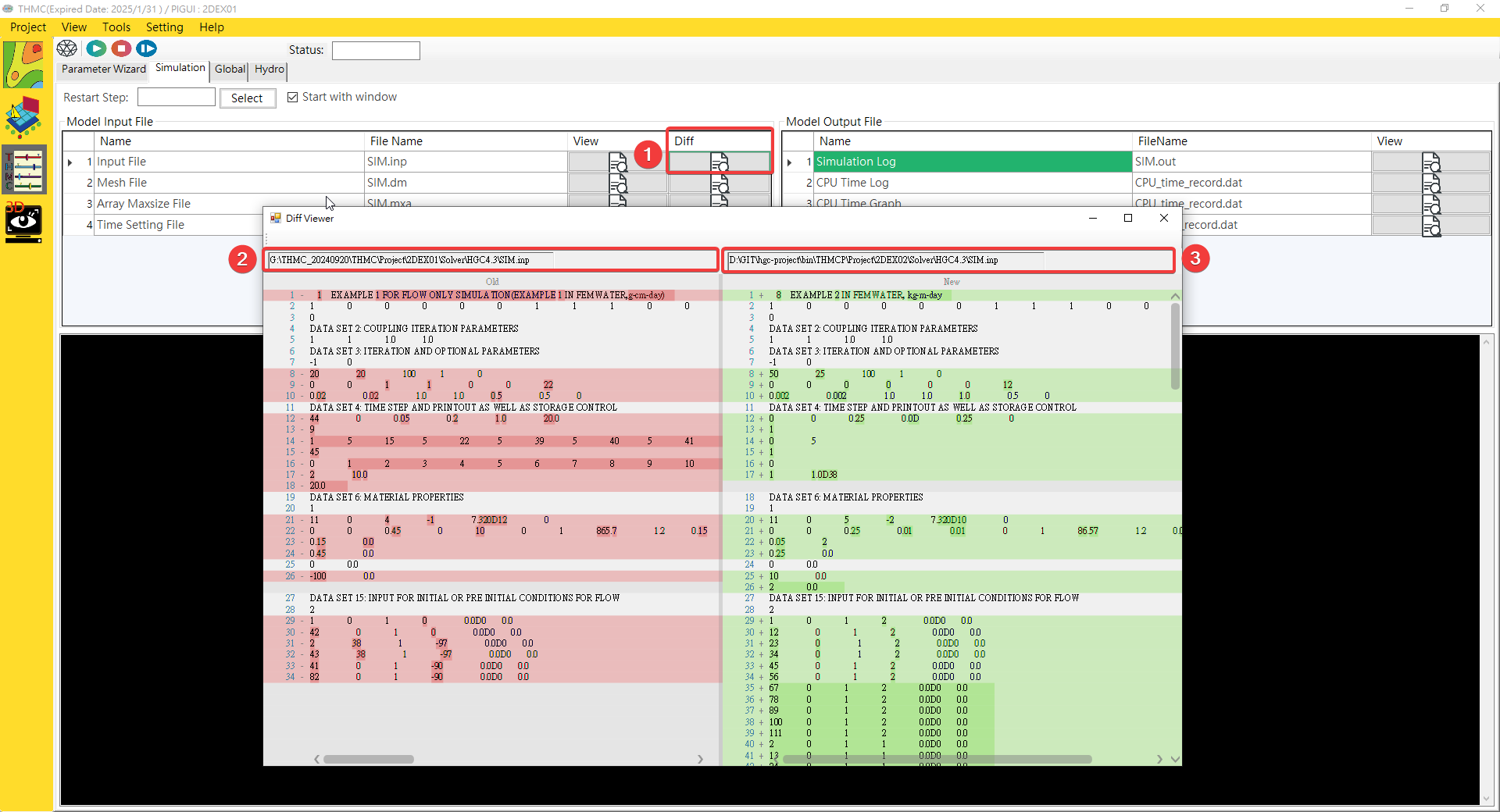
Fig. 4.1.24: File Compare
Compare: Use the mouse to click it and choose the new file which want to compare.Old File: Can drag and drop old file here.New File: Can drag and drop new file here.
¶ 4.2 Chemical Database
¶ 4.2.1 Start
Click Tools\Chemical Database GUI to start it.
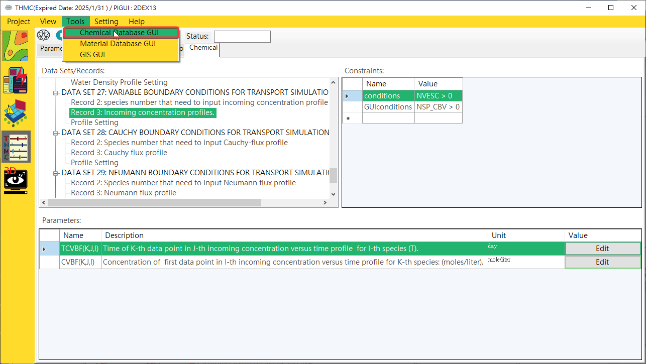
Fig. 4.2.1: Start Chemical Database
¶ 4.2.2 Function Blocks
The thermodynamic database user interface includes a function switching block and a data display editing block. Each block is described below. The thermodynamic database functional block is shown in Fig. 4.2.2.
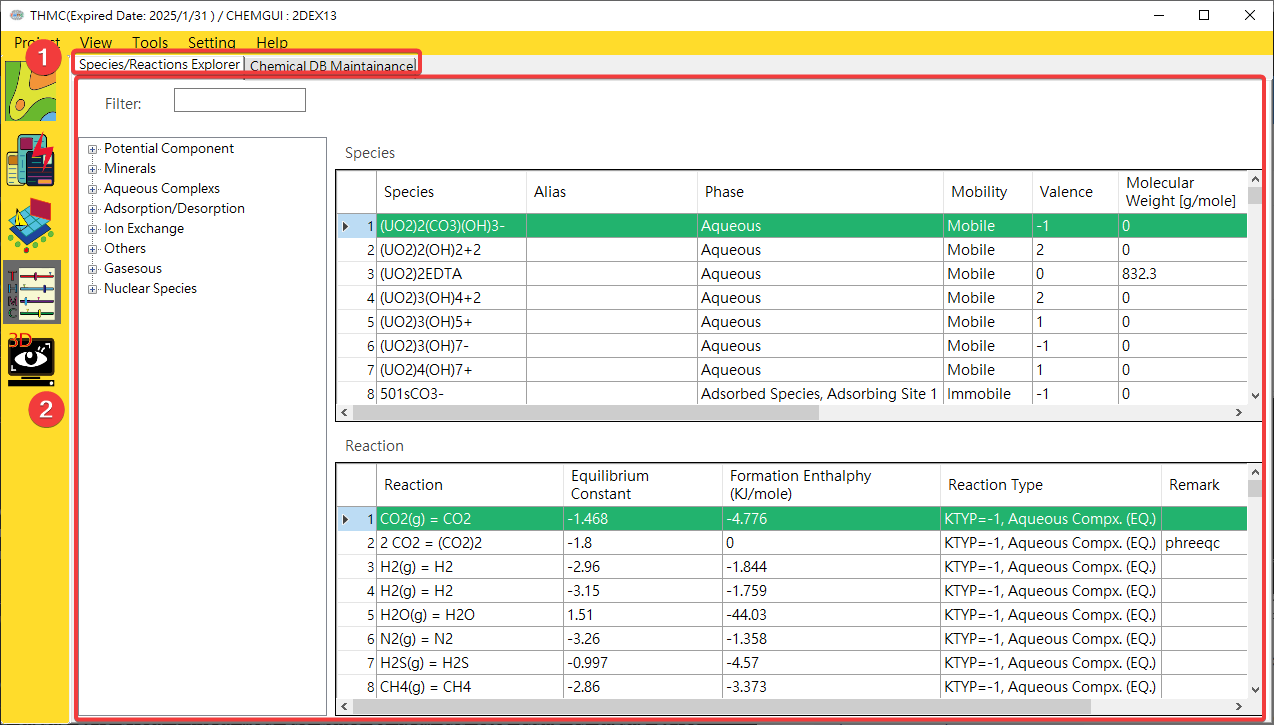
Fig. 4.2.2: Chemical Database Function Block
Function Page Switching Block: Use the mouse to click on each function page to switch to the [Chemical Species and Reaction Browser] or [Chemical Self-Library Maintenance] function page.Data display and editing block: This block can be used for data viewing and editing.
¶ 4.2.3 Functions
Chemical Browser: After clicking on the chemical species of interest, you can automatically find out the species-related parameters and participating reaction formulas, as shown inFig. 4.2.3.
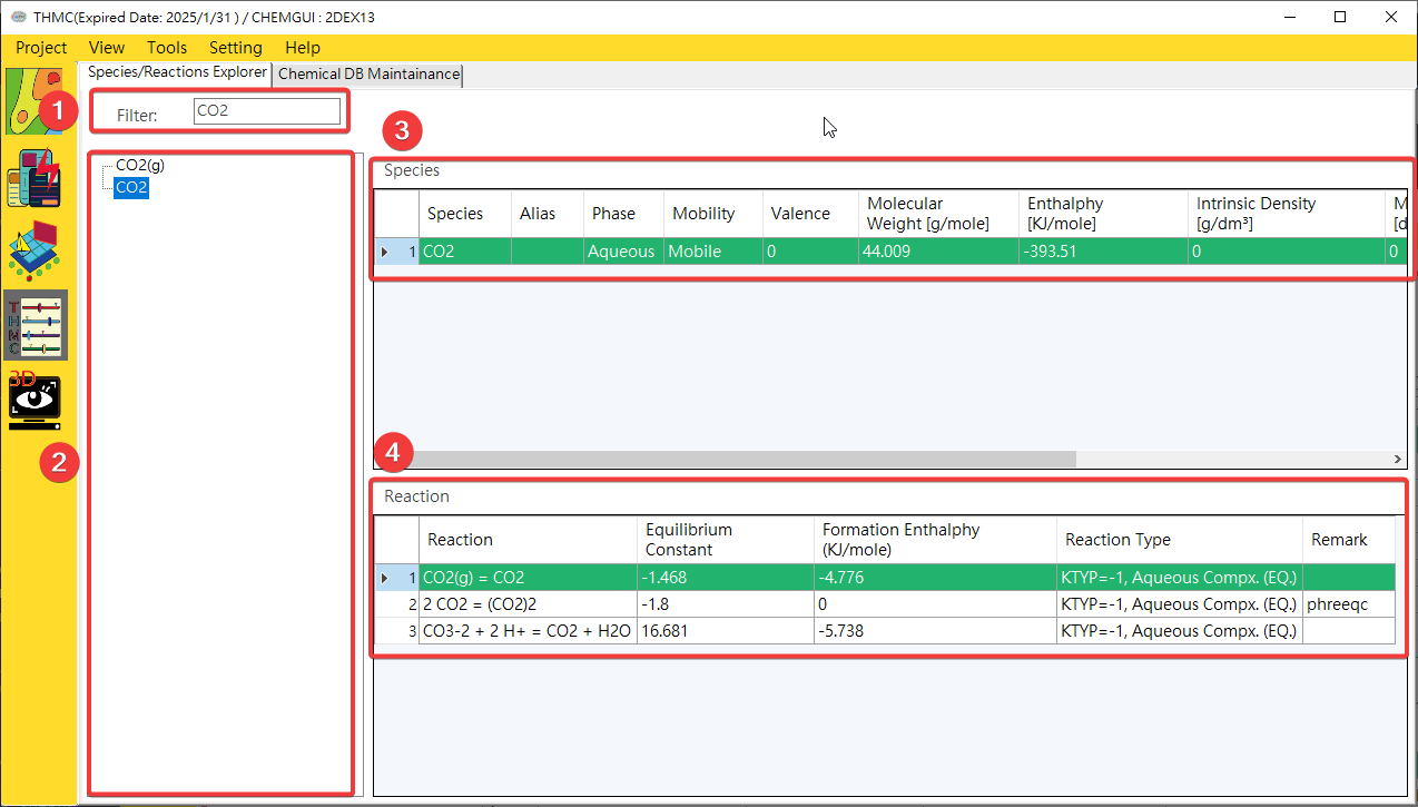
Fig. 4.2.3: Chemical Browser
1: Species Filter 2: Species Browser 3: Species Parameters 4: Reactions Include Selected Species
Chemical Editor: Provides data maintenance function for chemical species and reaction parameters, as shown inFig. 4.2.4andFig. 4.2.5.
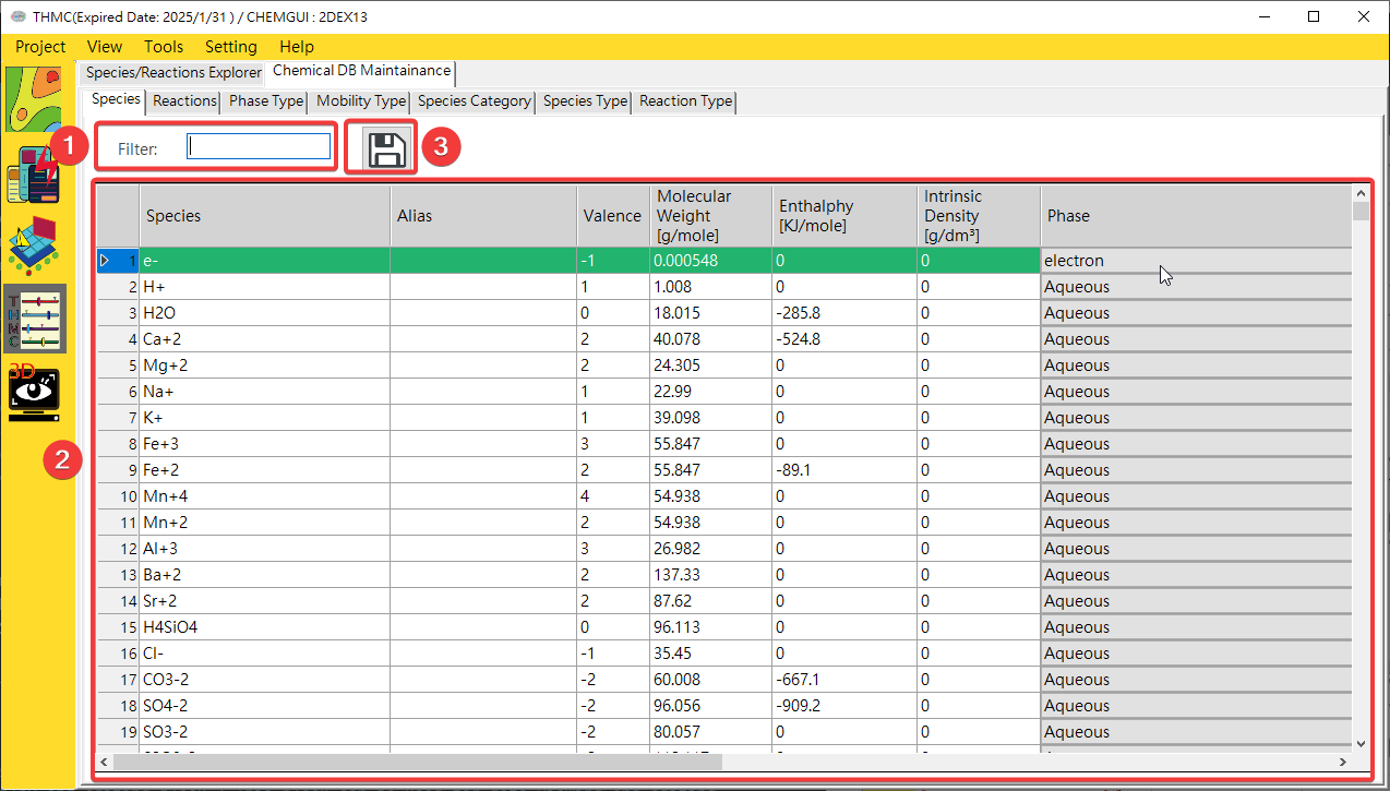
Fig. 4.2.4: Chemical Editor Function Block
1: Edit Functions 2: Add New
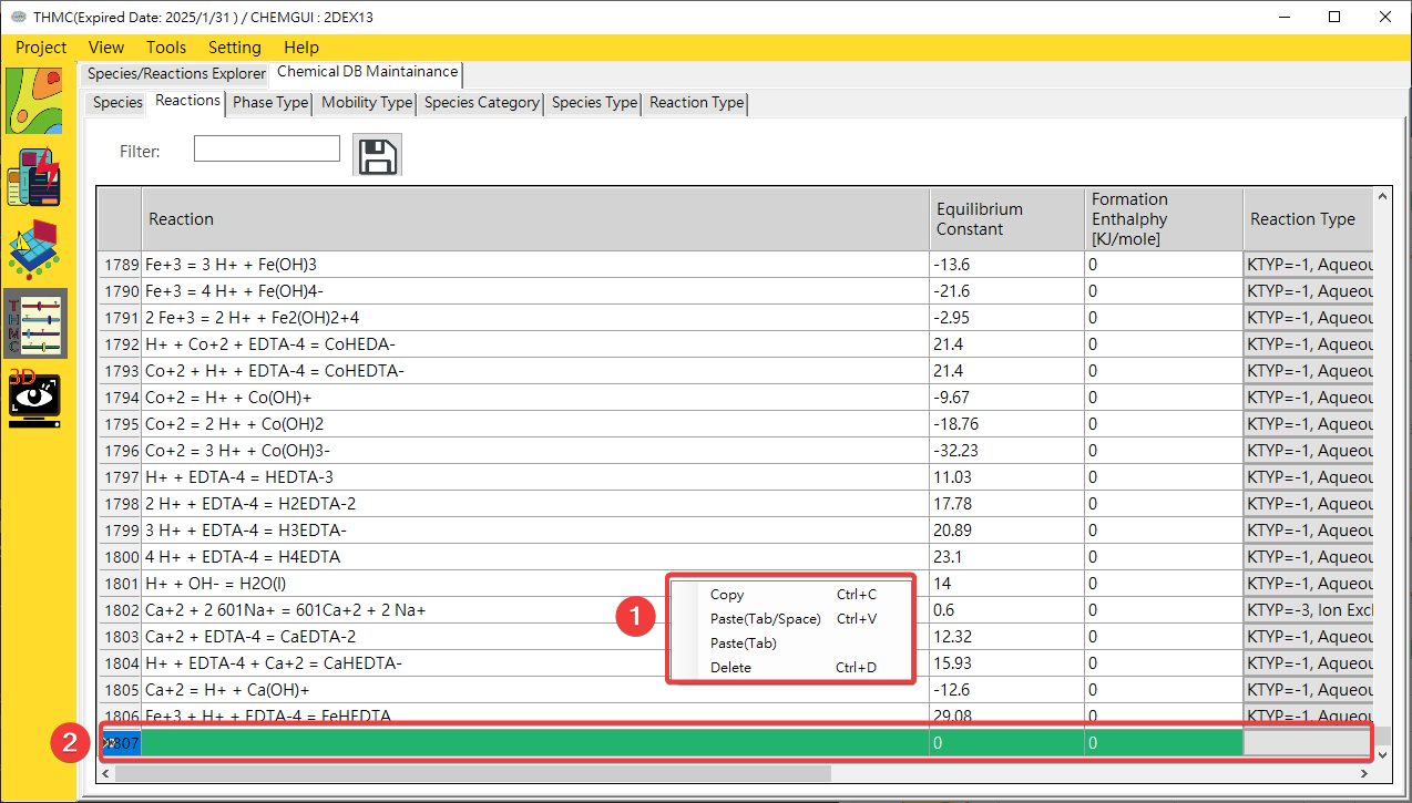
Fig. 4.2.5: Chemical Editor Edit Functions
1: Species Filter 2: Species Parameters Edit Area 3: Save
¶ 4.3 Material Database
¶ 4.3.1 Start
Click Tools\Material Database GUI to start it.
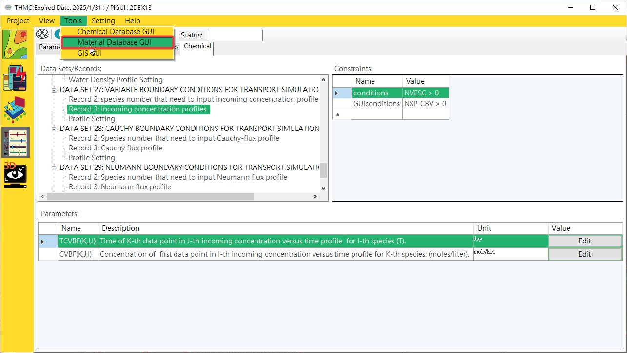
Fig. 4.3.1: Start Material Database
¶ 4.3.2 Function Blocks
The user interface of the formation material database includes a function switching block and a data display and editing block. The descriptions of each block are as follows, as shown in Fig. 4.3.2.
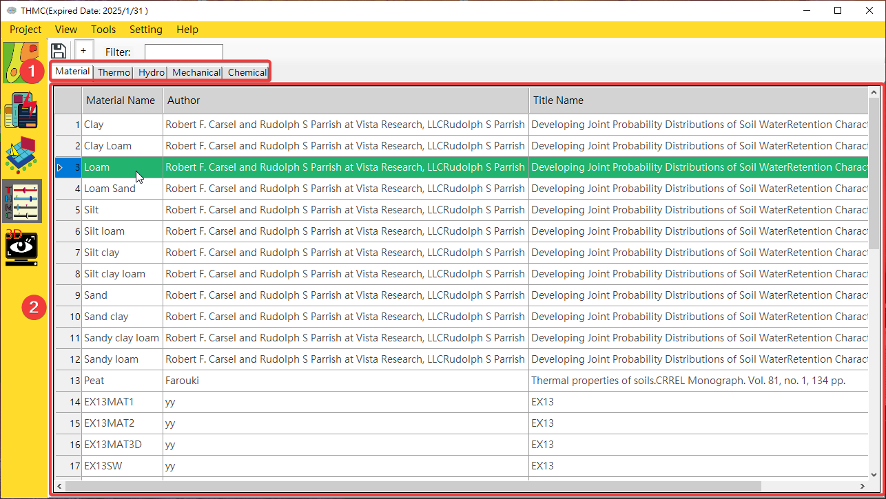
Fig. 4.3.2: Material GUI Function Block
Function Page Switching Block: Use the mouse to click on each function page to switch to the [Material], [Thermo], [Hydro],[Mechanical] and [Chemical]
¶ 4.3.3 Functions
Function pages to edit basic material data, thermal, hydrology, chemical and mechanical parameters. See Fig. 4.3.3 and Fig. 4.3.4.
2. Data Display Editing Block: Use the mouse to click on the content to edit.
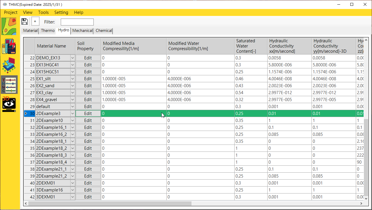
Fig. 4.3.3: Material GUI Module Pages
¶ 4.4 Benchmark
¶ 4.4.1 Start
Click Project\Benchmark to start it.
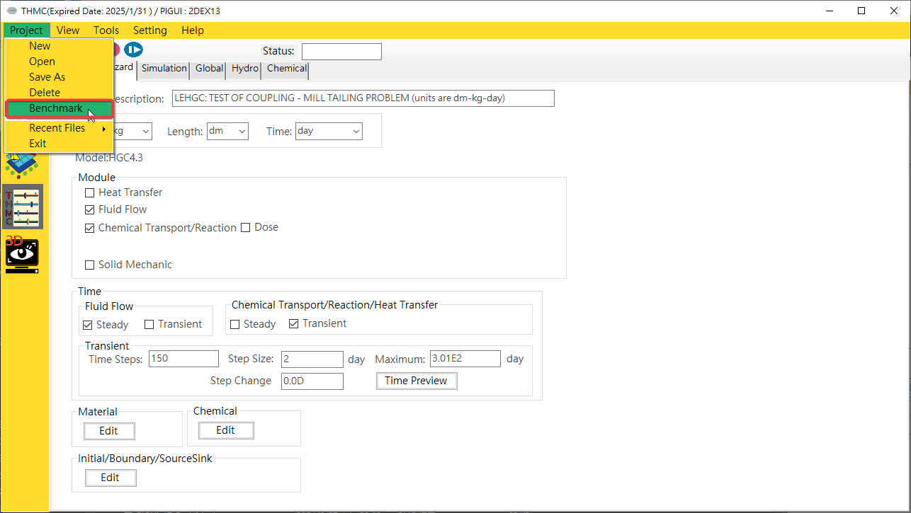
Fig. 4.4.1: Start Benchmark
¶ 4.4.2 Function Blocks
The thermodynamic database user interface includes a function switching block and a data display editing block. Each block is described below. The thermodynamic database functional block is shown in Fig. 4.4.2.
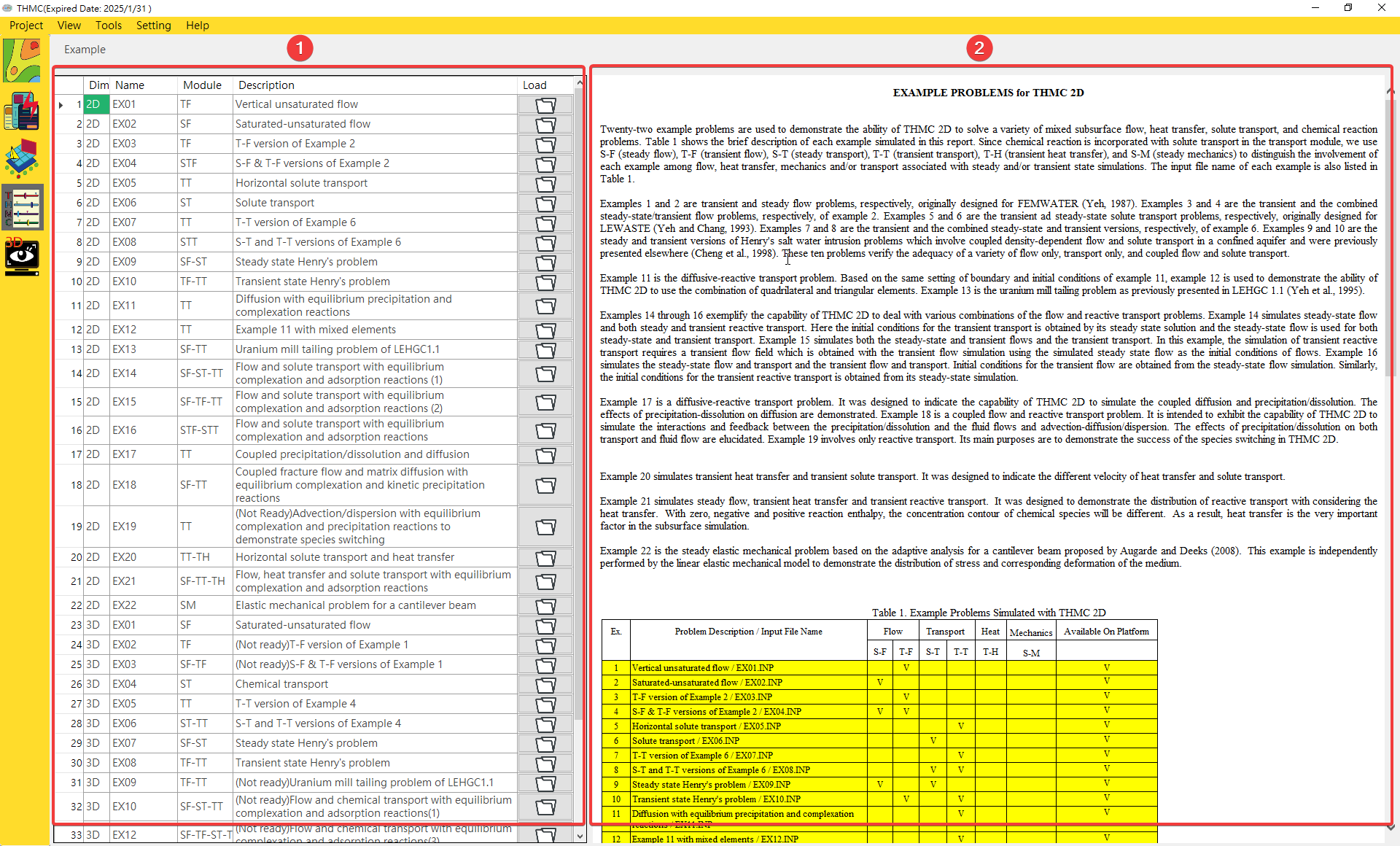
Fig. 4.4.2: Benchmark Function Blocks
Example Browser: Examples list.Example Information Display: This block can be used for example's introduction.
¶ 4.4.3 Functions
Example Selection: After clicking on theExample Browser, example introduction will be displayed onExample Information DisplayExample Execution: Click to load example and start simulation and post-processing, and will start theParaviewto display the visualization result as shown inFig. 4.4.4andFig. 4.4.5.
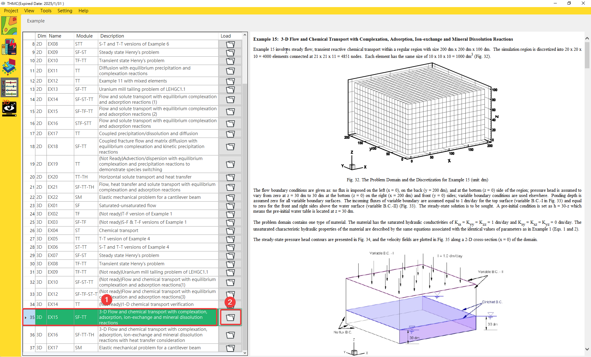
Fig. 4.4.3: Benchmark Functions
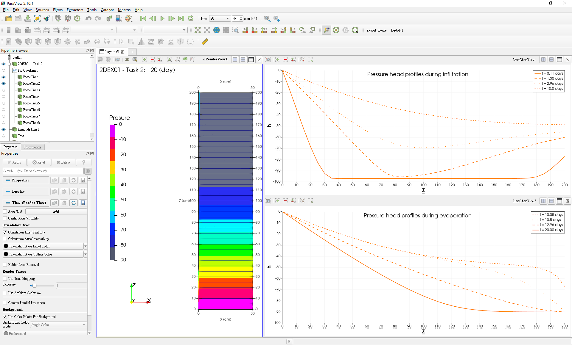
Fig. 4.4.4: Simulation Visualization 1
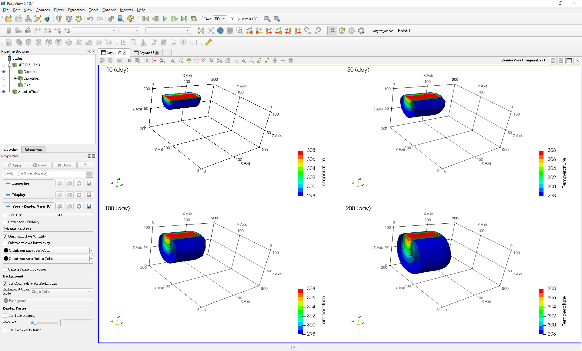
Fig. 4.4.5: Simulation Visualization 2