¶ 3.1 Geometry GUI
¶ 3.1.1 Function Blocks
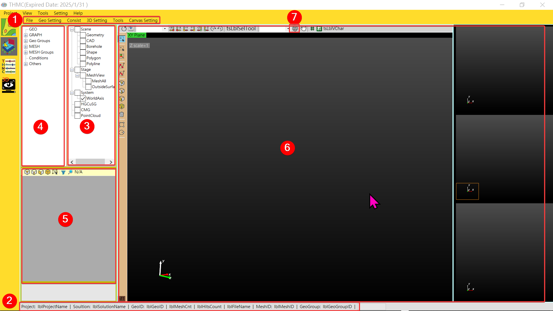
Function blocks as Fig. 3.1.1, include 6 blocks and Mesh Generator as following:
Menu and Toolstrip: Menu and toolstrip functions.Status Information: Realtime status information, include project/canvas and engineering.Layer Window: layer management functions.Data Window: Data classification tree structure display functions.Property Window: Parameter details display.Canvas: Graphic display area functions.Mesh Generator: Automatic mesh generation functions.
¶ 3.1.2 Menu and Toolstrip
Menu function list as Figure 3.1.2

-
File: File function menu.
a.New or Open solution: Open a new or existing saved solution.
Project is exclusive to the integration platform, and Solution is used for the geometric model GUI. The Solution will change depending on the Project. You can also create a solution for the GUI of a single geometric model.
b.Save Solution: Store existing solutions.
c.Close Solution(All): Close the existing solution, including clearing all data and canvas.
d.Load Point: Load the point data file of the geometric model (default geometry.txt).
e.Load Graph: Load the terrain data file of the geometric model (default graph.txt).
f.Load Stretch: Load the stretch setting file of the geometric model (default stretch.txt).
g.Load Mesh: Load mesh generator file.
g.Load DM: Load mesh DM file.
h.Import: Load the ESRI Shape file.
i.Adaptor: Convert CMG to HGC file.
j.SaveGeometryFolder: Back up all geometric model input files, including the above-mentioned Point, Graph and Stretch, for later loading.
k.Save Mesh Files: Back up the mesh file for later loading.
l.Load Selected Objects: Load selected objects.
m.Mesh File Header Setting: Mesh file header setting, for internal use of the program.
n.Preference settings: Set the spacing between repeated points (applicable to ESRI Shape input). If the distance between two points is less than this value, it will be regarded as a single point. -
Geo Setting: Geometry setting and geometry model setting menu.
a.Smart Quadrilateral: Automatically find all quadrilaterals with only four end points, and set corner points and boundary groups to meet quadrilateral mesh generation conditions.
b.Geo 2D Profile Mesh Intersect: Two-dimensional geometric mesh intersection -
Consist: Data integration functions.
a.Check InputData Integrity: To delete duplicate points, the setting value of File->Preference will be referred to.
b.Check MeshData Integrity: Add independent points to adjacent areas. -
3D: 3D Model Setting.
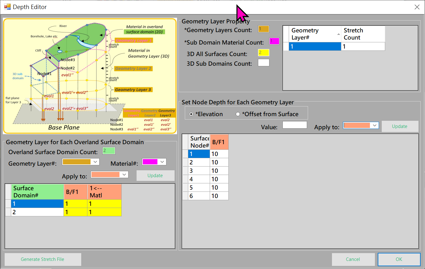
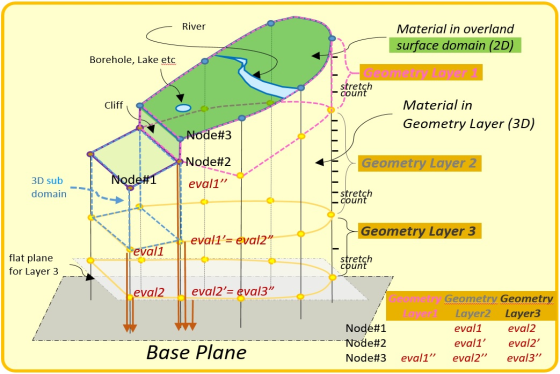
Depth EditorasFigure 3.1.3andFigure 3.1.4. Divided into geometry layers (Geometry Layer Property), the surface area corresponds to the geometry layer and the depth of each node in each layer. Related information is linked in the same color and provides storage functions.
Tools: Tools, such as options, etc.Canvas Setting: Canvas settings menu to change the canvas background color.
¶ 3.1.3 Status Information
Project Status: Real-time project information is displayed at the bottom of the window, including (displayed depending on data characteristics). See as asFigure 3.1.5Canvas Status: Information is shown above in red.Engineering Status: Displayed in black text on a gray background, such as mouse coordinates, etc.

¶ 3.1.4 Layer Window
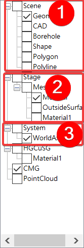
Layer Window as Figure 3.1.6
Scene: Show/hide Geometry, the rest of the Scene is used for reference.System: Show/hide the system XYZ coordinate axis origin.Stage: Different materials can be hidden or displayed below. MeshAll can quickly select all materials at once.
¶ 3.1.5 Data Window
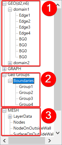
Data Window as Figure 3.1.7
GEO: The geometry is further divided into Domain and Edge according to the hierarchy.Geo Groups: Geometry group assembly.MESH: The grid assembly is divided into Nodes, Boundaries, Faces and Volumes according to the hierarchy.
¶ 3.1.6 Property Window
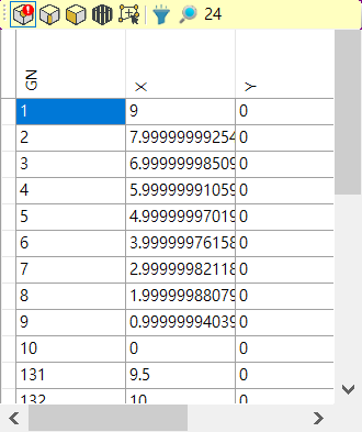
Property Window as Figure 3.1.8
Property Switching: Node, Edge and surface data switching.Property Data Selection: Data supports single or multiple selections.Data Block Sub Functions: Sub function of data block.Group Creation: Create a selected object group based on points, lines, and surfacs, and a single GeoGroupID will be automatically assigned.
¶ 3.1.7 Canvas
-
Basic Operation: Information (Tips) will be prompted when the mouse is temporarily placed on the function bar icon.
a. Zoom in: Mouse wheel up.
b. Zoom out: Mouse wheel down.
c. Move: Press and hold the middle mouse button and move.
d. Rotate: Press and hold the right mouse button and move.
e. Launch the menu: Right-click.
f. Hotkey W: wire frame.
g. Hotkey S: Draw surface. -
Horizontal Function Bar: Canvas functions. -
Vertical Function Bar: Object edit and selection functions. -
Draw Regular Polygon: Function description of drawing CAD regular polygons, see asFig. 3.1.9
a. TheCenter Pointcan be set freely, and the initial value is 0.
b. Give the widthWand heightH.
c.DensityThe smaller the value, the denser it is.
d. CheckHollowto indicate that the current polygon is hollowed out.

Draw Circle: Function description of drawing CAD circle, , see asFig. 3.1.10
a. TheCenter Pointcan be set freely, and the initial value is 0.
b. Give theRadius.
c. TheEdge countindicates the number of polygons to be used to approximate the circle.
d.Densitythe smaller the value, the denser it is.
e. CheckHollowto indicate that the current polygon is hollowed out.

¶ 3.1.8 Mesh Generator
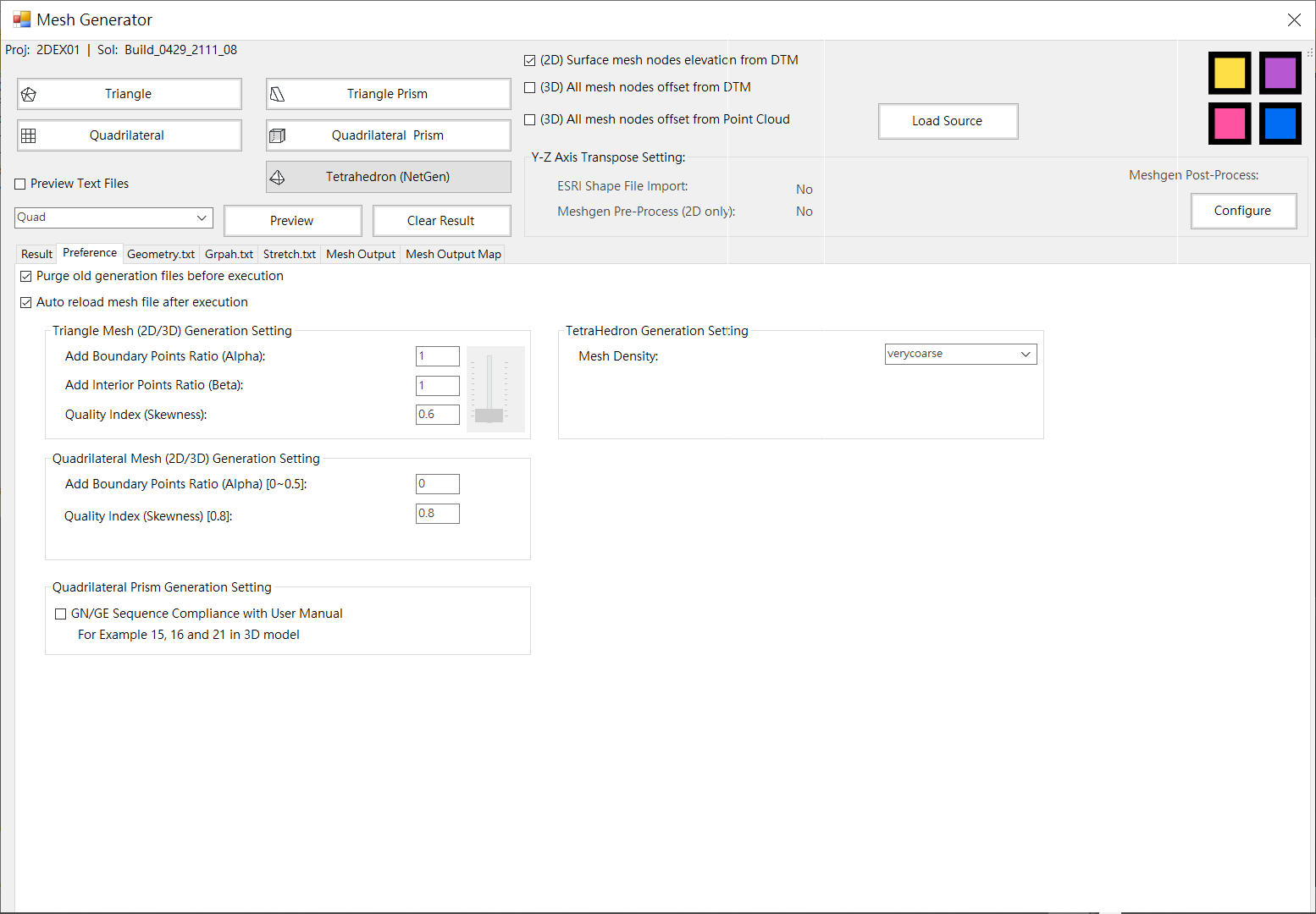
Mesh Generator as Figure 3.1.11
